Isuzu D-Max / Isuzu Rodeo (TFR/TFS). Manual — part 837
6E–77
3.2L ENGINE DRIVEABILITY AND EMISSIONS
ECM Diagnostic Trouble Codes
The following table lists the diagnostic trouble codes
supported a Tech 2 and to flash.If any DTCs not listed
here are displayed by a Tech 2, the Tech 2 data may be
faulty; notify the Tech 2 manufacturer of any DTCs
displayed that are not included in the following table.
ECM Diagnostic Trouble Codes
DTC
using a
Tech 2
Flash DTC
Description
Type
Illuminate MIL
P0101
61
MAF System Performance
B
Yes
P0102
61
MAF Sensor Circuit Low Frequency
A
Yes
P0103
61
MAF Sensor Circuit High Frequency
A
Yes
P0107
33
BARO Sensor Circuit Low Voltage
A
Yes
P0108
33
BARO Sensor Circuit High Voltage
A
Yes
P0112
23
IAT Sensor Circuit Low Voltage
A
Yes
P0113
23
IAT Sensor Circuit High Voltage
A
Yes
P0117
14
ECT Sensor Circuit Low Voltage
A
Yes
P0118
14
ECT Sensor Circuit High Voltage
A
Yes
P0121
21
TP System Performance
A
Yes
P0122
21
TP Sensor Circuit Low Voltage
A
Yes
P0123
21
TP Sensor Circuit High Voltage
A
Yes
P0131
15
HO2S Circuit Low Voltage Bank 1 Sensor 1
A
Yes
P0132
15
HO2S Circuit High Voltage Bank 1 Sensor 1
A
Yes
P0134
15
HO2S Circuit Insufficient Activity Bank 1 Sensor 1
A
Yes
P0171
44
Fuel Trim System Lean Bank 1
B
Yes
P0172
45
Fuel Trim System Rich Bank 1
B
Yes
P0201
31
Injector 1 Control Circuit
A
Yes
P0202
31
Injector 2 Control Circuit
A
Yes
P0203
31
Injector 3 Control Circuit
A
Yes
P0204
31
Injector 4 Control Circuit
A
Yes
P0205
31
Injector 5 Control Circuit
A
Yes
P0206
31
Injector 6 Control Circuit
A
Yes
P0336
29
58X Reference Signal Circuit
B
Yes
P0337
29
CKP Sensor Circuit Low Frequency
B
Yes
P0341
41
CMP Sensor Circuit Performance
B
Yes
P0342
41
CMP Sensor Circuit Low
B
Yes
P0351
42
Ignition 1 Control Circuit
A
Yes
P0352
42
Ignition 2 Control Circuit
A
Yes
P0353
42
Ignition 3 Control Circuit
A
Yes
P0354
42
Ignition 4 Control Circuit
A
Yes
P0355
42
Ignition 5 Control Circuit
A
Yes
P0356
43
Ignition 6 Control Circuit
A
Yes
P0502
24
VSS Circuit Low Input
B
Yes
P0562
66
System Voltage Low
D
No
P0563
66
System Voltage High
D
No

6E–78
3.2L ENGINE DRIVEABILITY AND EMISSIONS
DTC
using a
Tech 2
Flash DTC
Description
Type
Illuminate MIL
P0601
51
ECM Memory
A
Yes
P1171
44
Fuel System Lean During Acceleration
A
Yes
P1508
22
IAC System Low RPM
B
Yes
P1509
22
IAC System High RPM
B
Yes
6E–79
3.2L ENGINE DRIVEABILITY AND EMISSIONS
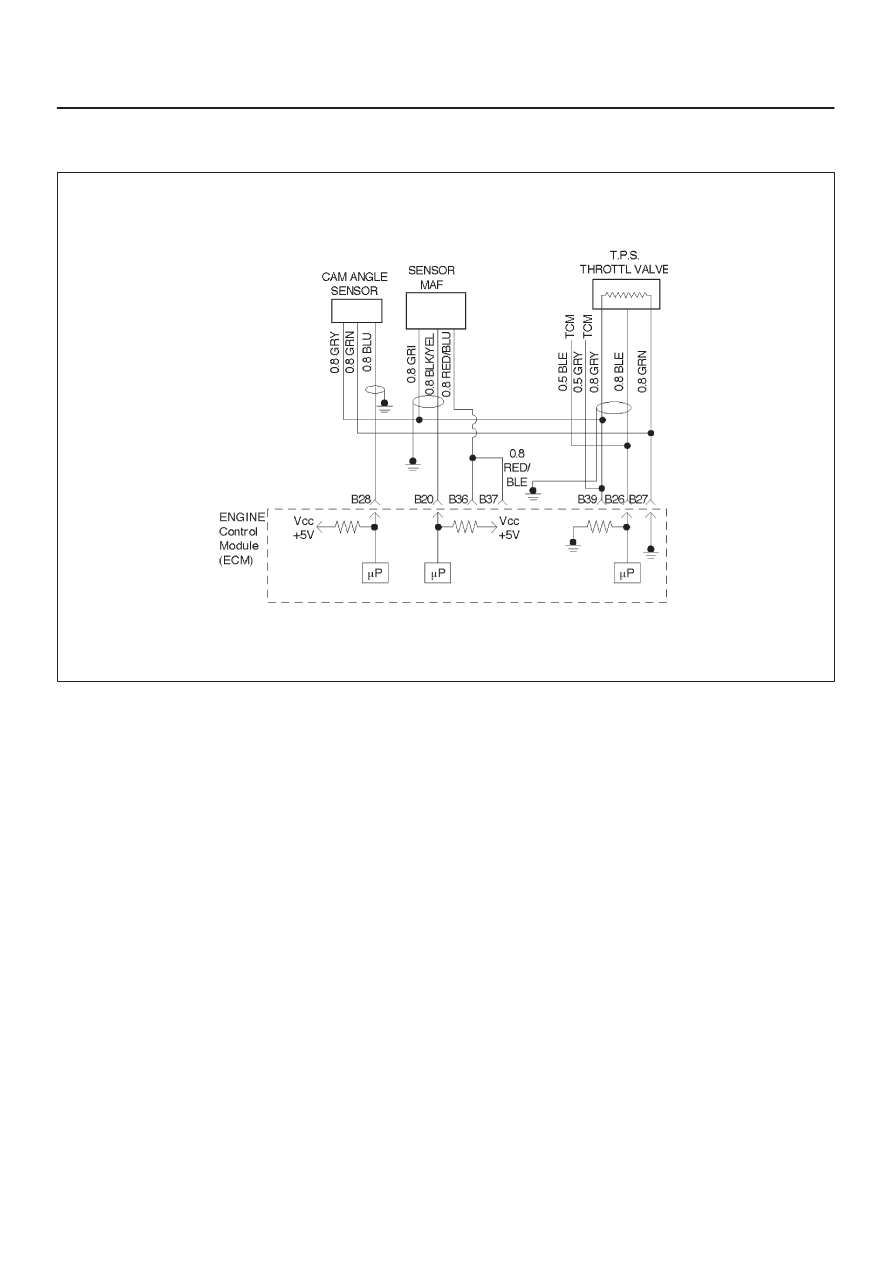
Diagnostic Trouble Code (DTC) P0101 (Flash DTC=61) MAF System
Performance
060RW077
Circuit Description
The mass air flow (MAF) sensor measures the amount of
air which passes through it into the engine during a given
time. The Engine Control Module ECM uses the mass air
flow information to monitor engine operating conditions
for fuel delivery calculations. A large quantity of air
entering the engine indicates an acceleration or high load
situation, while a small quantity or air indicates
deceleration or idle.
The MAF sensor produces a frequency signal which can
be monitored using a Tech 2. The frequency will vary
within a range of around 4 to 7 g/s at idle to around 25 to 40
g/s at maximum engine load. DTC P0101 will be set if the
signal from the MAF sensor does not match a predicted
value based on throttle position and engine RPM.
Conditions for Setting the DTC
D
The engine is running.
D
No TP sensor or BARO, CMP, CKP, MAF sensor DTCs
are set.
D
The Engine Speed is between 2800 r.p.m and 4500
r.p.m.
D
TP angle is between 1V and 3V.
D
IAT is between —14
°
C and 70
°
C.
D
Above conditions present for at least 3 second.
D
MAF signal frequency indicates an airflow significantly
higher or lower than a predicted value based on throttle
position and engine RPM for a total of 12.5 seconds
over a 25-second period of time.
Action Taken When the DTC Sets
D
The ECM will illuminate the malfunction indicator lamp
(MIL) after the second consecutive trip in which the
fault is detected.
D
The ECM calculates an airflow value based on idle air
control valve position, throttle position, RPM and
barometric pressure.
D
The ECM will store conditions which were present
when the DTC was set as Freeze Frame and in the
Failure Records data.
Conditions for Clearing the MIL/DTC
D
The ECM will turn the MIL “OFF” on the third
consecutive trip cycle during which the diagnostic has
been run and the fault condition is no longer present.
D
A history DTC P0101 will clear after 40 consecutive
warm-up cycles have occurred without a fault.
D
DTC P0101 can be cleared by using the Tech 2 “Clear
Info” function or by disconnecting the ECM battery
feed.
Diagnostic Aids
An intermittent may be caused by the following:
D
Poor connections.
D
Mis-routed harness.
D
Rubbed through wire insulation.

6E–80
3.2L ENGINE DRIVEABILITY AND EMISSIONS
D
Broken wire inside the insulation.
Refer to Intermittents under service category Symptoms.
Any un-metered air may cause this DTC to set. Check for
the following:
D
The duct work at the MAF sensor for leaks.
D
An engine vacuum leak.
D
The PCV system for vacuum leaks.
D
An incorrect PCV valve.
D
The engine oil dip stick not fully seated.
D
The engine oil fill cap loose or missing.
Test Description
Number(s) below refer to the step number(s) on the
Diagnostic Chart.
2. Using Freeze Frame and/or Failure Records data
may aid in locating an intermittent condition. If the
DTC cannot be duplicated, the information included
in the Freeze Frame and/or Failure Records data
can be useful in determining how many miles since
the DTC set. The Fail Counter and Pass Counter
can also be used to determine how many ignition
cycles the diagnostic reported a pass and/or a fail.
Operate the vehicle within the same Freeze Frame
conditions (RPM, load, vehicle speed , temperature,
etc.) that were noted. This will isolate when the
DTC failed.
For any test that requires back probing the ECM or
component harness connectors, use the Connector
Test Adapter Kit 5-8840-0385-0. Using this kit will
prevent any damage to the harness connector
terminals.
3. Any un-metered air may cause this DTC to set.
Check the PVC system for vacuum leaks. Also
inspect the dip stick for being pulled out. Check the
oil fill cap for being loose.
4. Verifies the signal circuit from the MAF sensor
electrical connector to the ECM.
5. Verifies whether a ground and B+ circuit is available.
6. Checks a signal circuit for an open.
7. Checks for a signal circuit shorted to B+.
DTC P0101 – MAF System Performance
Step
Action
Value(s)
Yes
No
1
Was the “On-Board Diagnostic (OBD) System Check”
performed?
—
Go to
Step 2
Go to
OBD
System
Check
2
1. Ignition “ON,” engine “OFF.”
2. Review the Freeze Frame and/or Failure Records
data for this DTC and note parameters.
3. Ignition “OFF” for 15 seconds.
4. Start the engine and operate the vehicle within the
conditions required for this diagnostic to run, and as
close to the conditions recorded in Freeze Frame
/Failure Records possible. (Special operating
conditions that need to be met before the ECM will
run this diagnostic (where applicable) are listed in
“Conditions for Setting the DTC”).
5. Using the Tech 2, select “DTC,” then enter the DTC
number which was set.
Does the Tech 2 indicate that this diagnostic failed this
ignition?
—
Go to
Step 3
Refer to
Diagnostic
Aids
3
1. Check for the following conditions:
D
Objects blocking the MAF sensor inlet screen;
D
Intake manifold vacuum leaks;
D
Vacuum leaks at throttle body;
D
Crankcase ventilation valve faulty, missing, or
incorrectly installed.
2. If a problem is found, repair as necessary.
Was a problem found?
—
Verify repair
Go to
Step 4
Нет комментариевНе стесняйтесь поделиться с нами вашим ценным мнением.
Текст