Isuzu D-Max / Isuzu Rodeo (TFR/TFS). Manual — part 836

6E–73
3.2L ENGINE DRIVEABILITY AND EMISSIONS
Idle Air Control (IAC) System Check
Step
Action
Value(s)
Yes
No
1
1. Ignition “OFF.”
2. Connect the IAC motor analyzer 5-8840-2312-0 to
the IAC valve.
3. Set the parking brake.
4. Block the wheels.
5. Turn the air conditioning “OFF.”
6. Idle the engine in Park (A/T) or Neutral (M/T).
7. Install the Tech 2. Display the RPM.
8. Use the IAC motor analyzer 5-8840-2312-0 to
extend and retract the IAC valve.
9. The engine speed should decrease and increase as
the IAC is cycled.
Does the RPM change?
—
Go to
Step 2
Go to
Step 3
2
RPM should change smoothly with each flash of the
IAC motor analyzer 5-8840-2312-0 light.
Does the RPM change within the range specified?
700-1500
RPM
Go to
Step 6
Go to
Step 3
3
Check the IAC passages.
Are the IAC passages OK?
—
Go to
Step 4
Go to
Step 5
4
Clear any obstruction from the IAC passages.
Is the action complete?
—
Verify repair
—
5
Replace the IAC. Refer to
On-Vehicle Service, Idle Air
Control Valve.
Is the action complete?
—
Verify repair
—
6
1. Install the appropriate IAC noid light from
5-8840-2312-0 into the Engine Control Module
harness.
2. Cycle the IAC motor analyzer J 39027-A and
observe the noid lights.
3. Both the lights should cycle red and green, but
never “OFF,” as the RPM is changed over its range.
Do the noid lights cycle red and green?
—
Go to
Step 7
Go to
Step 8
7
1. Use the other connector on the IAC motor analyzer
5-8840-2312-0 pigtail.
2. Check the resistance across the IAC coils.
Measure the resistance between terminal A and
terminal B.
3. Measure the resistance between terminal C and
terminal D.
Is the resistance within the specified range?
40-80 ohms
Go to
Step 9
Go to
Step 10
8
If the circuits did not test green and red, check the
following:
D
Faulty connector terminal contacts
D
Open circuits, including connections
D
Circuits shorted to ground or voltage
D
Faulty Engine Control Module connection or
Engine Control Module.
Are repairs necessary?
—
Go to
Step 13
—

6E–74
3.2L ENGINE DRIVEABILITY AND EMISSIONS
Idle Air Control (IAC) System Check
(Cont'd)
Step
No
Yes
Value(s)
Action
9
1. Check the resistance between the IAC terminal B
and terminal C.
2. Check the resistance between the IAC terminal A
and terminal D.
Is the resistance infinite?
—
Go to
Step 11
Go to
Step 12
10
Replace the IAC. Refer to
On-Vehicle Service, Idle Air
Control Valve.
Is the action complete?
—
Go to
Step 7
—
11
Check the IAC valve and circuit.
Are the IAC valve and circuit OK?
—
Refer to
Diagnostic
Aids
Go to
Step 12
12
Replace the IAC. Refer to
On-Vehicle Service, Idle Air
Control Valve.
Is the action Complete?
—
Go to
Step 9
—
13
Repair as necessary.
Is the action complete?
—
Go to
Step 6
—
6E–75
3.2L ENGINE DRIVEABILITY AND EMISSIONS
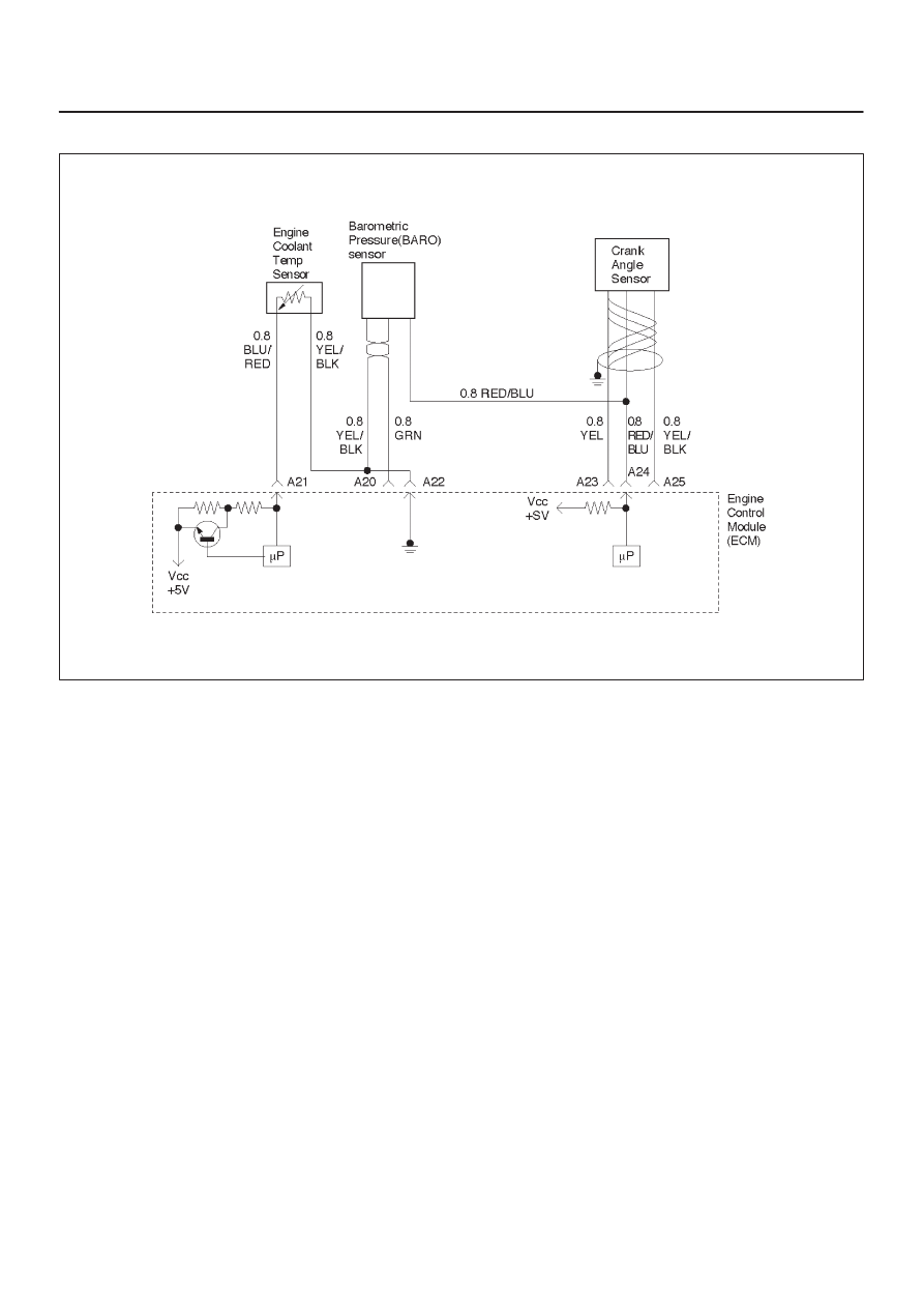
Barometric Pressure (BARO) Output Check
060RW072
Circuit Description
The barometric pressure (BARO) sensor measures the
changes in the intake BARO which result from engine
load (intake manifold vacuum) and engine speed
changes; and converts these into a voltage output. The
Engine Control Module ECM sends a 5-volt reference
voltage to the BARO sensor. As the BARO changes, the
output voltage of the sensor also changes. By monitoring
the the sensor output voltage, the ECM knows the BARO.
A lower pressure (low voltage) output voltage will be
about 1-2 volts at idle. Higher pressure (high voltage)
output voltage will be about 4-4.8 volts at wide open
throttle. The BARO sensor is also used, under certain
conditions, to measure barometric pressure, allowing the
ECM to make adjustments for different altitudes.
Test Description
IMPORTANT:
Be sure to used the same diagnostic test
equipment for all measurements.
The number(s) below refer to the step number(s) on the
Diagnostic Chart.
1. Applying 34 kpa (10 Hg) vacuum to the BARO
sensor should cause the voltage to be 1.5-2.1 volts
less than the voltage at step 1. Upon applying
vacuum to the sensor, the change in voltage should
be instantaneous. A slow voltage change indicates
a faulty sensor.
IMPORTANT:
Make sure the electrical connector
remains securely fastened.
2. Disconnect the sensor from the bracket. Twist the
sensor with your hand to check for an intermittent
connection. Output changes greater than 0.10 volt
indicate a bad sensor.

6E–76
3.2L ENGINE DRIVEABILITY AND EMISSIONS
Barometric Pressure (BARO) Output Check
Step
Action
Value(s)
Yes
No
1
1. Turn the ignition “OFF” and leave it “OFF” for 15
seconds.
2. Ignition “ON.” Don’t crank engine.
3. The Tech 2 should indicate a barometric pressure
(BARO) sensor voltage.
4. Compare this scan reading to scan reading of a
known good vehicle obtained using the exact same
procedure as in Steps 1–4.
Is the voltage reading the same +/–0.40 volt?
—
Go to
Step 2
Go to
Step 5
2
1. Disconnect the BARO sensor and plug
inletmanifold.
2. Connect a hand vacuum pump to the BARO sensor.
3. Start the engine.
4. Apply 34 kpa (10 Hg) of vacuum and note the
voltage change.
Is the voltage change 1.5-2.1 volts less than step 1?
—
Go to
Step 3
Go to
Step 4
3
No trouble found. Check the sensor cover for leakage
or restriction.
Does the cover supply vacuum to the BARO sensor
only?
—
Go to
Step 5
Go to
Step 4
4
Repair the material to block.
Is the action complete?
—
Verify repair
—
5
Check the sensor connection.
Is the sensor connection good?
—
Go to
Step 5
Go to
Step 6
6
Replace the sensor. Refer to
On-Vehicle Service,
BARO Sensor.
Is the action complete?
—
Verify repair
—
7
Repair the poor connection.
Is the action complete?
—
Verify repair
—
Нет комментариевНе стесняйтесь поделиться с нами вашим ценным мнением.
Текст