Isuzu D-Max / Isuzu Rodeo (TFR/TFS). Manual — part 1838
7A1-14 CONSTRUCTION AND FUNCTION
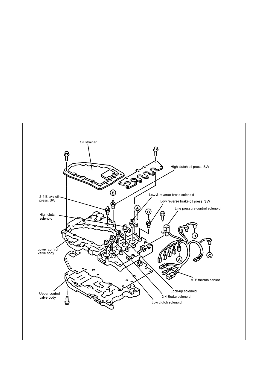
CONTROL VALVE
•
Employing the direct electronic control (Direct Electronic Shift Control: DESC) for the clutch pressure has
simplified the oil pressure circuit, reduced the number of functional components and made the control
valve compact.
•
The control valve body is divided into the upper body and lower body. All solenoids, oil pressure switch
and ATF thermo sensor are installed to the lower body.
•
Three-way valve type solenoids providing high responsibility are employed. Some of the solenoids are
switched between ON and OFF and others repeat ON and OFF at 50Hz (duty cycle system).
Functionally, some supply output pressure when power is not supplied and others drain the output
pressure.
•
When the solenoid is driven based on the signal from the TCM, the oil pressure is changed. The valve is
operated by the difference of the oil pressure.
Figure 22. Construction of Valve Body

CONSTRUCTION AND FUNCTION 7A1-15
Line Pressure Solenoid
•
The line pressure solenoid is turned ON or OFF according to the signal from the TCM. It switches the
line pressure between high and low pressure.
•
While no power is supplied, the solenoid supplies high pressure.
Shift Solenoid
•
The shift solenoid is of the duty cycle type which are turned ON or OFF at 50Hz. The ratio of the ON and
OFF time can be freely controlled in the range of 0 - 100%.
•
While no power is supplied, the solenoid supplies output pressure.
•
The low clutch solenoid adjusts the low clutch pressure, the high clutch solenoid the high clutch pressure,
the 2-4 brake solenoid the 2-4 brake pressure and the low & reverse brake solenoid the low & reverse
brake pressure respectively.
Lock-up Solenoid
•
The lock-up solenoid is of the duty cycle type which is turned ON or OFF at 50Hz. The ratio of ON and
OFF time can be freely controlled in the range of 0-100%.
•
While no power is supplied, the solenoid drains the output pressure.
Figure 23. Shift Solenoid
Figure 24. Lock-up Solenoid
Figure 25. Location of Solenoid

7A1-16 CONSTRUCTION AND FUNCTION
Control Valve Fail-safe Function
•
To prevent interlocking due to engagement of more than three clutches and brakes at the same time, the
2-4 brake fail-safe valve A and B, and the low & reverse brake fail-safe valve A and B are provided.
•
When oil pressure is generated in the high clutch and the low clutch, the 2-4 brake solenoid is turned ON
to drain the oil pressure applied to the 2-4 brake.
•
When oil pressure is generated in the high clutch or 2-4 brake, the low & reverse brake solenoid is turned
ON to drain the oil pressure applied to the low & reverse brake.
Figure 26. Fail-safe Function
Oil Pressure Switch
•
The oil pressure switch detects the oil pressure supply condition to the clutch and brake and sends the
detection result to the TCM.
•
The oil pressure switch is turned ON when the oil pressure reaches the switch working pressure and
turned OFF when the pressure decreases below the specified value.
•
The high clutch oil pressure switch detects the high clutch oil pressure, 2-4 brake oil pressure switch the
2-4 brake oil pressure, and the low & reverse brake oil pressure switch the low & reverse brake oil
pressure respectively.
Figure 27. Oil Pressure Switch
Figure 28. Location of Oil Pressure Switch
CONSTRUCTION AND FUNCTION 7A1-17
ATF Thermo Sensor
•
The ATF thermo sensor detects the ATF temperature in the oil pan and sends signal to the TCM.
•
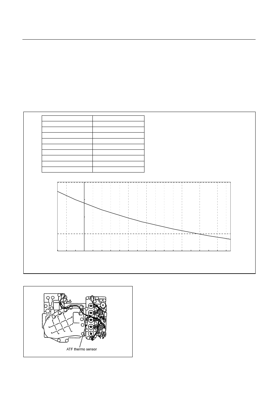
The ATF thermo sensor is of the thermister type that the resistance value changes according to the ATF
oil temperature.
•
The lower is the ATF temperature, the larger is the resistance, and vice versa.
•
When the ATF temperature exceeds 145
°
C, the TCM lights up the ATF temperature warning lamp in the
meter. When the ATF temperature decreases below 128
°
C, the ATF temperature warning lamp goes out.
•
The ATF thermo sensor is installed to the lower control valve body and integrated with the harness
assembly.
10.0
100.0
1,000.0
10,000.0
100,000.0
-30 -20 -10
0
10 20 30 40 50 60
70 80 90 100 110 120 130 140 150 160
ATF Temperature (°C)
Resistance (
)
Figure 29. Characteristic of Thermo Sensor
Figure 30. Location of Thermo Sensor
ATF Temperature (
°
C) Resistance
(Approximately)
−
30
°
C 29,613.7
Ω
0
°
C 6,028.0
Ω
10
°
C 3,822.1
Ω
30
°
C 1,681.7
Ω
50
°
C 819.1
Ω
100
°
C 117.6
Ω
128
°
C 98.3
Ω
135
°
C 84.6
Ω
145
°
C 68.8
Ω
Нет комментариевНе стесняйтесь поделиться с нами вашим ценным мнением.
Текст