Isuzu D-Max / Isuzu Rodeo (TFR/TFS). Manual — part 1839
7A1-18 CONSTRUCTION AND FUNCTION
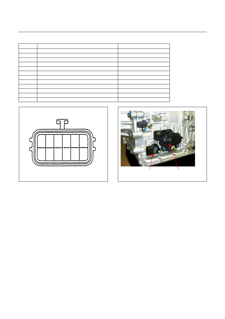
Terminal Assembly
Pin No.
Connected to
Connected TCMPin No.
6 Line
Pressure
Solenoid
B23
12
Low & Reverse Brake Oil Pressure Switch
B12
5
Low & Reverse Brake Duty Solenoid
B6
11 Ground
Return
B22
4
Lock-up Duty Solenoid
B17
10
High Clutch Duty Solenoid
B8
3
Low Clutch Duty Solenoid
B9
9
2-4 Brake Duty Solenoid
B7
2 Oil
Thermo
Sensor
B4
8
Oil Thermo Sensor Ground
B14
1
High Clutch Oil Pressure Switch
B20
7
2-4 Brake Oil Pressure Switch
B1
1
2
3
4
5
6
8
9
10
11
12
7
Terminal Assembly
Inhibitor Switch
Figure 31. Pin Assignment
Figure 32. Location of Terminal Assembly
CONSTRUCTION AND FUNCTION 7A1-19
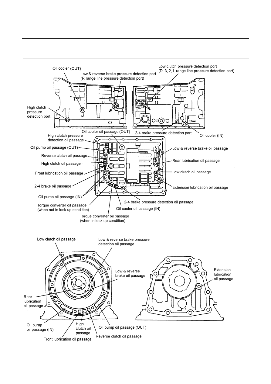
OIL PASSAGE
Figure 33. Oil Passage of Transmission Case

7A1-20 CONSTRUCTION AND FUNCTION
Figure 34. Oil Passage of Oil Pump
PARKING FUNCTION
•
By setting the select lever to the P range, the parking pawl is engaged with the parking gear and fixes the
output shaft.
•
By the movement of the select lever, the manual shaft on the side surface of the AT is moved. The
manual plate and parking rod in the AT are interlocked with the manual shaft. When the manual shaft
moves, the parking rod end pushes up the parking pawl.
•
The parking pawl is engaged with the parking gear when pushed up, and fixes the output shaft.
•
When the clutch is disengaged, it returns to the original position by the force of the return spring fixed to
the parking pawl.
Figure 35. Parking Function

CONSTRUCTION AND FUNCTION 7A1-21
INHIBITOR SWITCH
•
The inhibitor switch is installed on the right side of the transmission main unit to detect the select lever
position.
•
The inhibitor switch is connected with the starter SW circuit. The engine cannot be started when the
select lever is at any position other than the P or N range.
•
By moving the select lever, the combination of the inhibitor switch pins is changed. The current range of
TCM is detected based on the combination of the pins.
10 7 3 2 4 8 5 1 9 6
P
R
N
D
3
2
L
6
3
4
5
10
9
8
7
2
1
Terminal Assembly
Inhibitor Switch
Figure 36. Pin Assignment
Figure 37. Location of Inhibitor Switch
Нет комментариевНе стесняйтесь поделиться с нами вашим ценным мнением.
Текст