Isuzu D-Max / Isuzu Rodeo (TFR/TFS). Manual — part 1342
8–288 ELECTRICAL-BODY AND CHASSIS
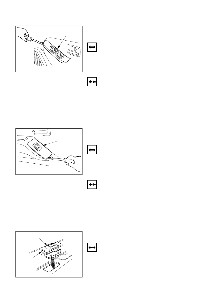
DRIVER SEAT SIDE POWER WINDOW & DOOR
LOCK SWITCH
(4 DOORS MODEL)
Removal
1. Remove the switch by pushing the spring with the tip
of a screwdriver.
2. Disconnect the connector.
Switch
825RV098
Installation
To install, follow the removal steps in the reverse order.
FRONT PASSENGER’S POWER WINDOW &
DOOR LOCK SWITCH
(4 DOORS MODEL)
Removal
1. Remove the switch by pushing the spring with the tip
of a screwdriver.
2. Disconnect the connector.
Switch
825RV086
REAR POWER WINDOW & DOOR LOCK
SWITCH-LH & RH
Removal
1. Remove the switch by pushing the spring with the tip
of a screwdriver.
2. Disconnect the connector.
Switch
Spring
825RV096
Installation
To install, follow the removal steps in the reverse order.
This illustration is based on RHD
This illustration is based on RHD
ELECTRICAL-BODY AND CHASSIS 8–289
Installation
To install, follow the removal steps in the reverse order.
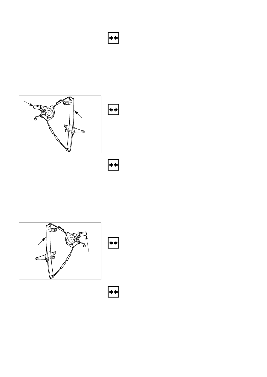
DRIVER SEAT SIDE POWER WINDOW MOTOR
Removal
1. Window Regulator ASM
•
Refer to the removal steps of the WINDOW
REGULATOR/POWER WINDOW MOTOR in Section
10 “BODY”.
2. Power Window Motor
•
Loosen the fixing bolts to remove the power
window motor from the regulator.
2.Power window motor
1.Window
regulator
ASM
825RV091
Installation
To install, follow the removal steps in the reverse order.
FRONT PASSENGER’S POWER WINDOW
MOTOR
Removal
1. Window Regulator ASM
•
Refer to the removal steps of the WINDOW
REGULATOR/POWER WINDOW MOTOR in Section
10 “BODY”.
2. Power Window Motor
•
Loosen the fixing bolts to remove the power
window motor from the regulator.
2.Power window
motor
1.Window
regulator
ASM
825RV090
Installation
To install, follow the removal steps in the reverse order.

8–290 ELECTRICAL-BODY AND CHASSIS
REAR POWER WINDOW MOTOR-LH & RH
Removal and Installation
Refer to the “DRIVER SEAT SIDE POWER WINDOW
MOTOR” removal and installation steps in this section.

ELECTRICAL-BODY AND CHASSIS 8–291
Power Window Relay
Check continuity between the relay terminals.
1 - 5 . . . . . . . . . . . . . . . . . . . . No continuity
(When battery voltage is applied between 2 and 4)
1 - 5 . . . . . . . . . . . . . . . . . . . . Continuity
4
1
3
2
5
2
1
3
4
5
060RV005
Driver Seat Side Power Window & Door Lock Switch
1. Harness Side Connector Circuit
Disconnect the switch connector, and check voltage
and continuity between the harness side connector
terminals as shown in the following table.
10
9
8
7
6
5
4
3
2
1
Terminal
Wire
Connecting to
Check item
Connecting
Check condition
Standard
No.
color
terminal
2
G/R
Power window
Voltage
2-Ground
Starter SW “ON”
Approx.
relay
12V
1
L/R
Power window
Continuity
1 – 10
—
Continuity
10
L/W
motor
5
B
Ground
Continuity
5-Ground
—
Continuity
Front Passenger’s Power Window & Door Lock Switch
1. Harness Side Connector Circuit
Disconnect the switch connector, and check voltage
and continuity between the harness side connector
terminals as shown in the following table.
10
9
8
7
6
5
4
3
2
1
INSPECTION AND REPAIR
B-8
Harness side
D-5
Harness side
D-10
Нет комментариевНе стесняйтесь поделиться с нами вашим ценным мнением.
Текст