Isuzu D-Max / Isuzu Rodeo (TFR/TFS). Manual — part 1343
8–292 ELECTRICAL-BODY AND CHASSIS
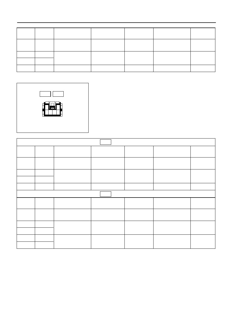
Rear Power Window Switch-LH & RH
1. Harness Side Connector Circuit
Disconnect the switch connector, and check voltage
and continuity between the harness side connector
terminals as shown in the following tables.
1
3 4 5 6
2
Terminal
Wire
Connecting to
Check item
Connecting
Check condition
Standard
No.
color
terminal
9
G/R
Power window
Voltage
9-Ground
Starter SW “ON”
Approx.
relay
12V
6
L/R
Power window
Continuity
6 – 10
—
Continuity
10
L/W
motor
5
B
Ground
Continuity
5-Ground
—
Continuity
(RR–LH)
Terminal
Wire
Connecting to
Check item
Connecting
Check condition
Standard
No.
color
terminal
4
G/R
Power window
Voltage
4-Ground
Starter SW “ON”
Approx.
relay
12V
5
L/R
Power window
Continuity
5 – 6
—
Continuity
6
BR/W
motor
3
B
Ground
Continuity
3-Ground
—
Continuity
(RR–RH)
Terminal
Wire
Connecting to
Check item
Connecting
Check condition
Standard
No.
color
terminal
4
G/R
Power window
Voltage
4-Ground
Starter SW “ON”
Approx.
relay
12V
5
L/R
Power window
Continuity
5 – 6
—
Continuity
6
BR/W
motor
3
B
Ground
Continuity
3 – 1
—
Continuity
1
B
Harness side
D-12
D-12
D-16
D-16

ELECTRICAL-BODY AND CHASSIS 8–293
Driver Seat Side Power Window Motor
1. Driver Seat Side Power Window & Door Lock Switch
Connector Circuit
Disconnect the switch connector, apply the battery
voltage (12V) to the harness side connector terminals
and check operation.
10
9
8
7
6
5
4
3
2
1
2. Driver Seat Side Power Window Motor Connector
Circuit
Disconnect the switch connector, apply the battery
voltage (12V) to the motor side connector terminals
and check operation.
1
2
M
DOWN
UP
825RV092
Harness side
Motor side
D-5
D-1
Connecting terminals
Operation direction
1 (L/R)
10 (L/W)
–
+
DOWN
+
–
UP
Connecting terminals
Operation direction
1
2
+
–
DOWN
–
+
UP
8–294 ELECTRICAL-BODY AND CHASSIS
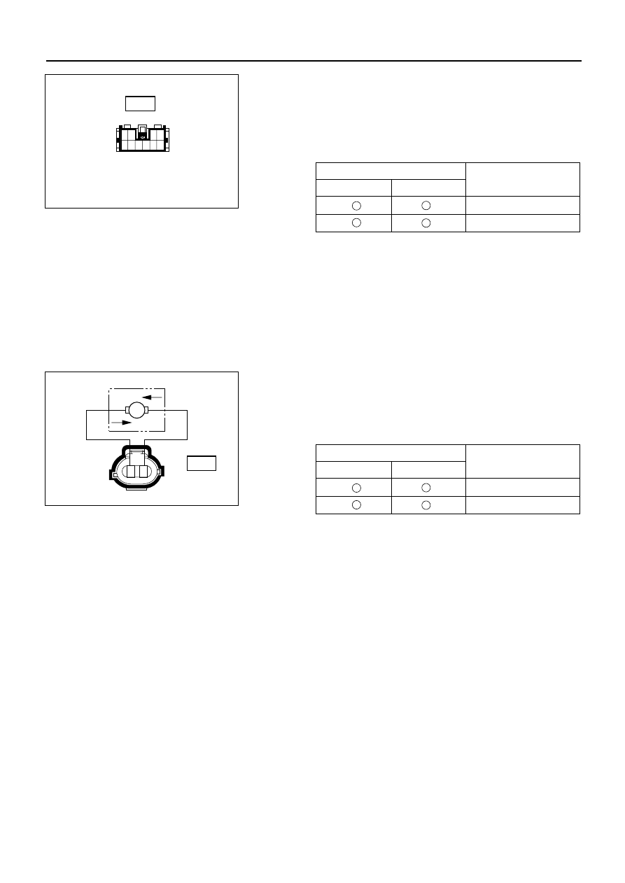
Front Passenger’s Power Window Motor
1. Front Passenger’s Power Window Switch & Door
Lock Switch Connector Circuit
Disconnect the motor connector, apply the battery
voltage (12V) to the harness side connector terminals
and check operation.
10
9
8
7
6
5
4
3
2
1
2. Front Passenger’s Power Window Motor Connector
Circuit
Disconnect the switch connector, apply the battery
voltage (12V) to the motor side connector terminals
and check operation.
1
2
M
DOWN
UP
825RV092
Harness side
Motor side
D-10
D-6
Connecting terminals
Operation direction
6 (L/R)
10 (L/W)
–
+
DOWN
+
–
UP
Connecting terminals
Operation direction
1
2
+
–
DOWN
–
+
UP
ELECTRICAL-BODY AND CHASSIS 8–295
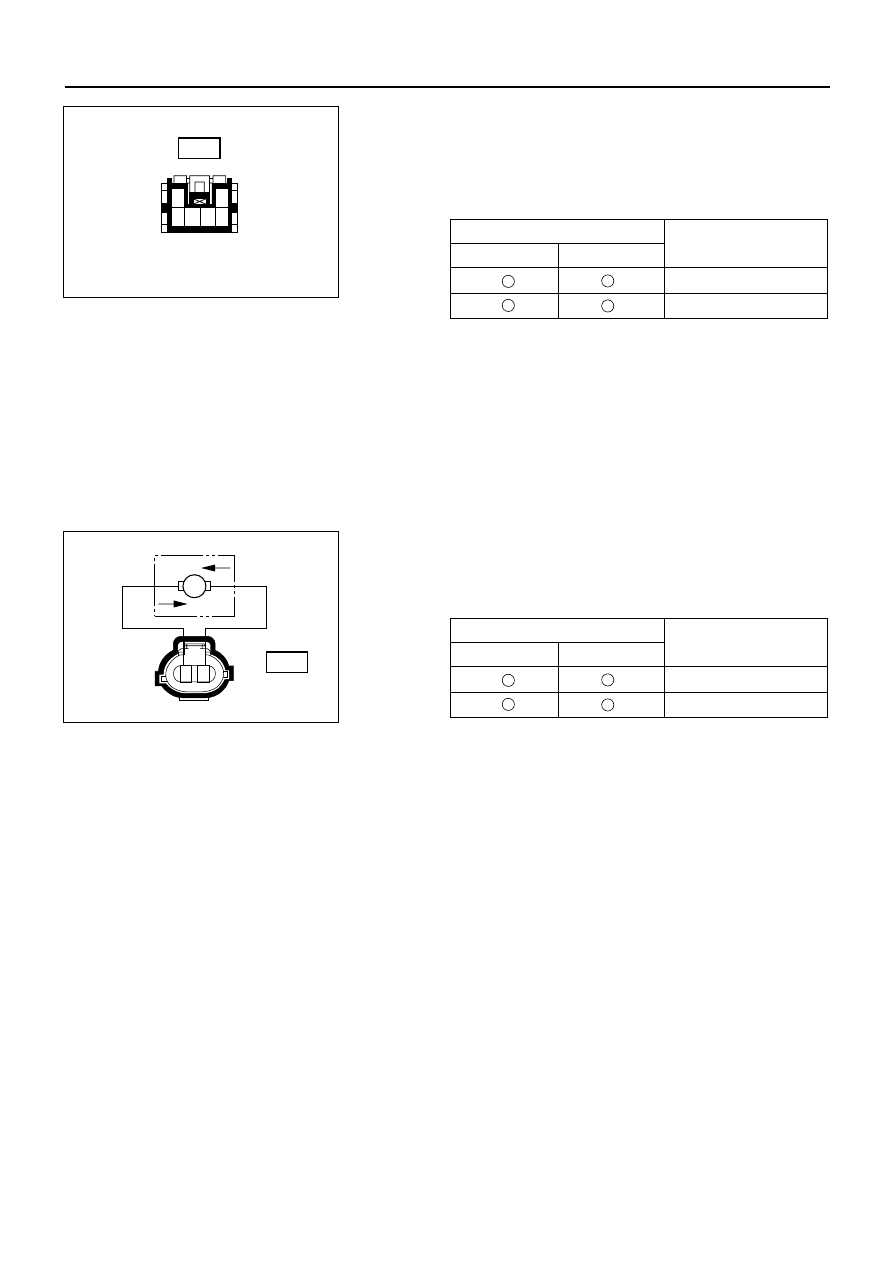
Rear Passenger’s Power Window Motor-LH
1. Rear Power Window Switch-LH Connector Circuit
Disconnect the motor connector, apply the battery
voltage (12V) to the harness side connector terminals
and check operation.
1
3 4 5 6
2
2. Rear Power Window Motor-LH Connector Circuit
Disconnect the switch connector, apply the battery
voltage (12V) to the motor side connector terminals
and check operation.
1
2
M
DOWN
UP
825RV092
Harness side
Motor side
D-12
D-11
Connecting terminals
Operation direction
5 (L/R)
6 (BR/W)
–
+
DOWN
+
–
UP
Connecting terminals
Operation direction
1
2
+
–
DOWN
–
+
UP
Нет комментариевНе стесняйтесь поделиться с нами вашим ценным мнением.
Текст