Isuzu D-Max / Isuzu Rodeo (TFR/TFS). Manual — part 1712
6D3-6 STARTING AND CHARGING SYSTEM
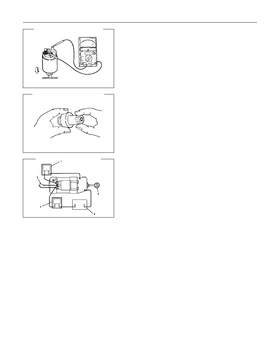
Continuity of Contacts
With the plunger faced downward, push down the magnetic
switch. In this state, check for continuity between terminals B
and M. Replace, if there is no continuity (i.e., contacts are
faulty).
Pinion
Check if the pinion rotates smoothly in drive direction by hand,
or if it is locked when it is rotated in reverse. If not, replace the
pinion.
Characteristic Test
For easily confirming the characteristics, conduct the noload
test as follows:
Rating as short as 30 seconds requires rapid testing.
Fix the starter on the test bench, and wire as shown in
illustration. When the switch is closed, the current flows and
the starter runs under no load. At this time, measure current,
voltage and speed to check if they satisfy the standard.
Legend
1 Volt Meter
2 Revolution Indicator
3 Battery
4 Ammeter
5 Switch
STARTING AND CHARGING SYSTEM 6D3-7
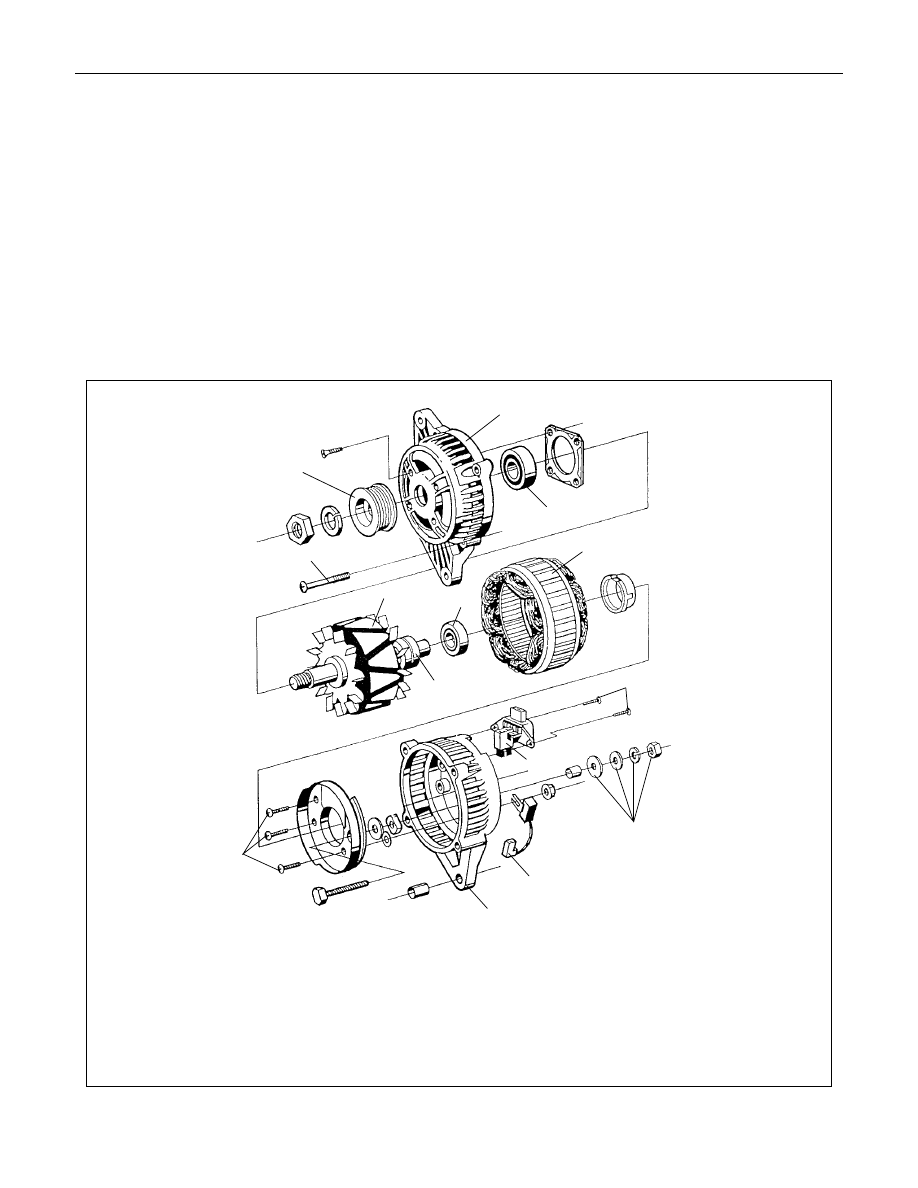
Charging System
General Description
The charging system is an IC integral regulator charging
system and its main components are connected as shown in
illustration.
The regulator is a solid state type and it is mounted along with
the brush holder assembly inside the generator installed on the
rear end cover.
The generator does not require particular maintenance such as
voltage adjustment. The rectifier connected to the stator coil
has eight diodes to transform AC voltage into DC voltage.
This DC voltage is connected to the output terminal of
generator.
Legend
1 Startor assembly
2 Housing
3 Slipring
4 Screws (2)
5 Regulator
6.Bolt (4)
7 Rectifier assembly
8 Retaining assembly
9 B+ terminal nut and washer
10 Pulley
11 Rotor assembly
12 Ball bearing
2
11
12
2
8
5
4
3
1
11
7
6
10
9
6D3-8 STARTING AND CHARGING SYSTEM
General On-Vehicle Inspection
The operating condition of charging system is indicated by the
charge warning lamp. The warning lamp comes on when the
starter switch is turned to "ON" position. The charging system
operates normally if the lamp goes off when the engine starts.
If the warning lamp shows abnormality or if undercharged or
overcharged battery condition is suspected, perform diagnosis
by checking the charging system as follows:
1. Check visually the belt and wiring connector.
2. With the engine stopped, turn the stator switch to "ON"
position and observe the warning lamp.
If lamp does not come on:
Disconnect wiring connector from generator, and ground
the terminal "L" on connector side.
If lamp comes on:
Repair or replace the generator.
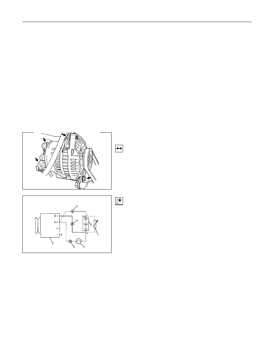
Generator
Removal
1. Disconnect battery ground cable.
2. Move drive belt tensioner to loose side using wrench then
remove drive belt.
3. Disconnect terminal "B" wiring connector and connector.
4. Remove generator assembly.
Generator Power and Circuit Diagram
Inspection
Legend
1 Load resistor, set parallel to battery
2 Battery
3 Voltmeter
4 Ammeter
5 Ignition Lock
6 Charge Telltale
7 Generator
1. Disconnect battery.
2. Close off connecting cable from alternator terminal "B+".
3. Set ammeter (measuring range 100A) in disconnected line.
4. Connect controllable load resistor to battery terminal.
5. Set resistor in front of connection to "O"; connect first to
battery, then to resistor.
6. Connect tachometer.
7. Connect
oscilloscope
according
to
manufacturer's
instructions.
8. Connect battery.
9. Start engine and read off resulting current at various engine
speeds.
STARTING AND CHARGING SYSTEM 6D3-9
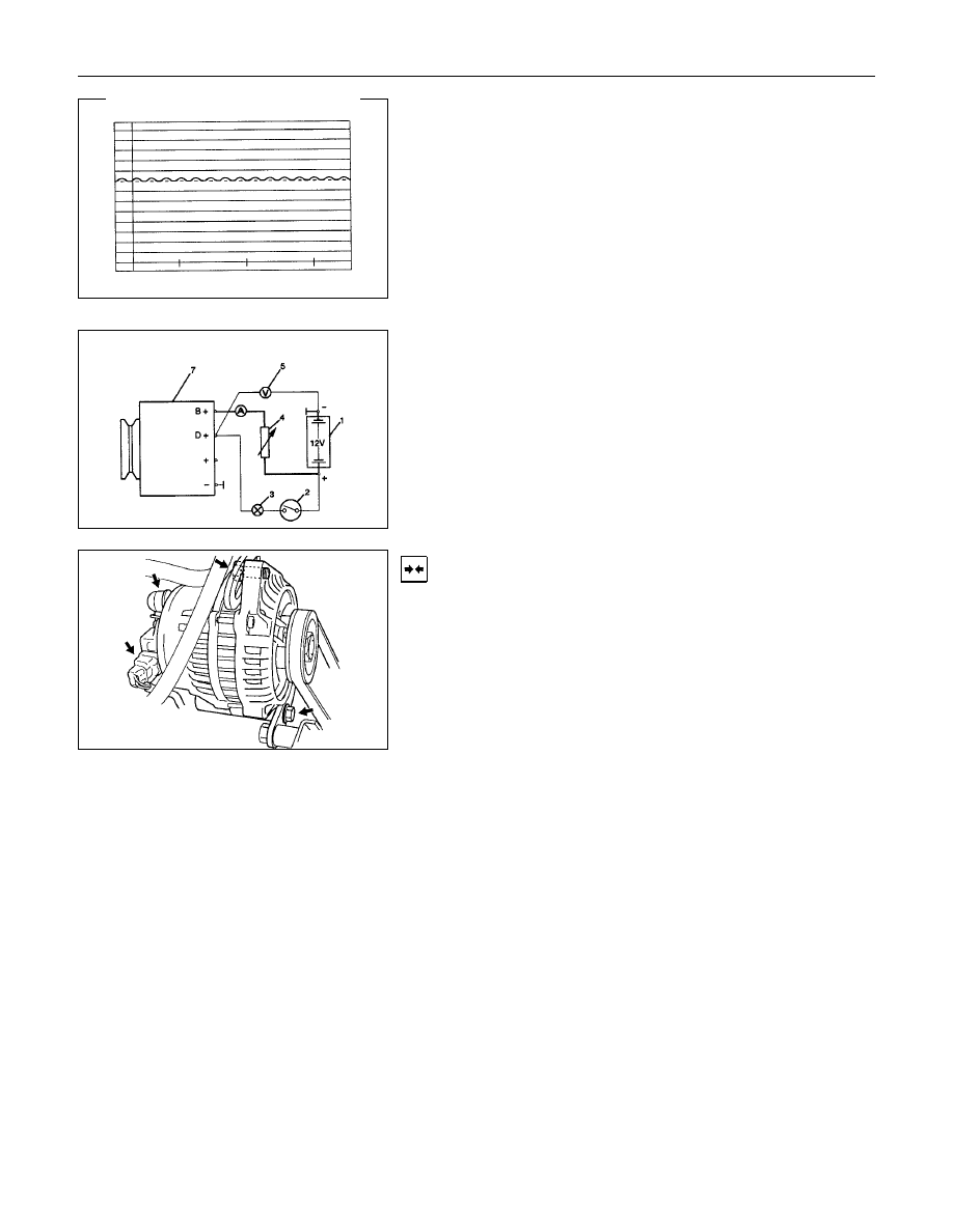
Generator Power
1. Adjust load resistor, if the required load currents are not
attained.
2. The shape of the voltage curves on oscilloscope curve
should be regular.
3. Test value: 5 to 7A.
4. If the required minimum current intensity is not attained, or if
the oscilloscope picture shows variations, the alternator
should be overhauled.
Regulated Voltage Circuit Diagram
Legend
1 Battery
2 Ignition Lock
3 Charge Telltale
4 Resistor, for attainment of load current with the battery set in
series
5 Voltmeter
6 Ammeter
7 Generator
Installation
1. Install generator assembly and bring generator assembly to
the position to be installed.
2. Install generator assembly and tighten to the specified
torque.
Torque:
Long bolt: 35 N
⋅⋅⋅⋅m (3.6 kgf⋅⋅⋅⋅m)
Short bolt: 20 N
⋅⋅⋅⋅m (2.0 kgf⋅⋅⋅⋅m)
3. Connect wiring harness connector.
4. Move drive belt tensioner to loose side using a wrench, then
install drive belt to normal position.
5. Reconnect battery ground cable.
Нет комментариевНе стесняйтесь поделиться с нами вашим ценным мнением.
Текст