Isuzu D-Max / Isuzu Rodeo (TFR/TFS). Manual — part 1711

6D3-2 STARTING AND CHARGING SYSTEM
Starting System
General Description
Cranking Circuit
The cranking system consists of a battery, starter, starter
switch, starter relay, etc. These main components are
connected.
Starter
The cranking system employs a magnetic type reduction
starter in which the motor shaft is also used as a pinion shaft.
When the starter switch is turned on, the contacts of magnetic
switch are closed, and the armature rotates. At the same time,
the plunger is attracted, and the pinion is pushed forward by
the shift lever to mesh with the ring gear.
Then, the ring gear runs to start the engine. When the engine
starts and the starter switch is turned off, the plunger returns,
the pinion is disengaged from the ring gear, and the armature
stops rotation. When the engine speed is higher than the
pinion, the pinion idles, so that the armature is not driven.
Service Precaution
CAUTION:
Always use the correct fastener in the proper location.
When you replace a fastener, use ONLY the exact part
number for that application. ISUZU will call out those
fasteners that require a replacement after removal. ISUZU
will also call out the fasteners that require thread lockers
or thread sealant. UNLESS OTHERWISE SPECIFIED, do
not use supplemental coatings (Paints, greases, or other
corrosion inhibitors) on threaded fasteners or fastener
joint interfaces. Generally, such coatings adversely affect
the fastener torque and the joint clamping force, and may
damage the fastener. When you install fasteners, use the
correct tightening sequence and specifications. Following
these instructions can help you avoid damage to parts and
systems.
Diagnosis
Condition
Possible cause
Correction
Starter does not run
Charging failure
Repair charging system
Battery Failure
Replace Battery
Terminal connection failure
Repair or replace terminal connector
and/or wiring harness
Starter switch failure
Repair or replace starter switch
Starter failure
Repair or replace starter
STARTING AND CHARGING SYSTEM 6D3-3
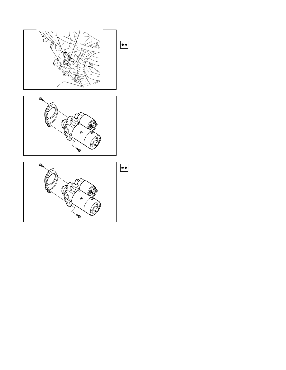
Starter
Removal
1. Remove the battery ground cable.
2. Remove harness connectors (1) and (2).
3. Remove bolts from starter.
Installation
1. Install starter assembly.
2. Install mounting bolts and tighten bolts to specified torque.
Torque: 51 N
⋅⋅⋅⋅m (5.2 kgf⋅⋅⋅⋅m)
3. Connect harness.
4. Reconnect the battery ground cable.
6D3-4 STARTING AND CHARGING SYSTEM
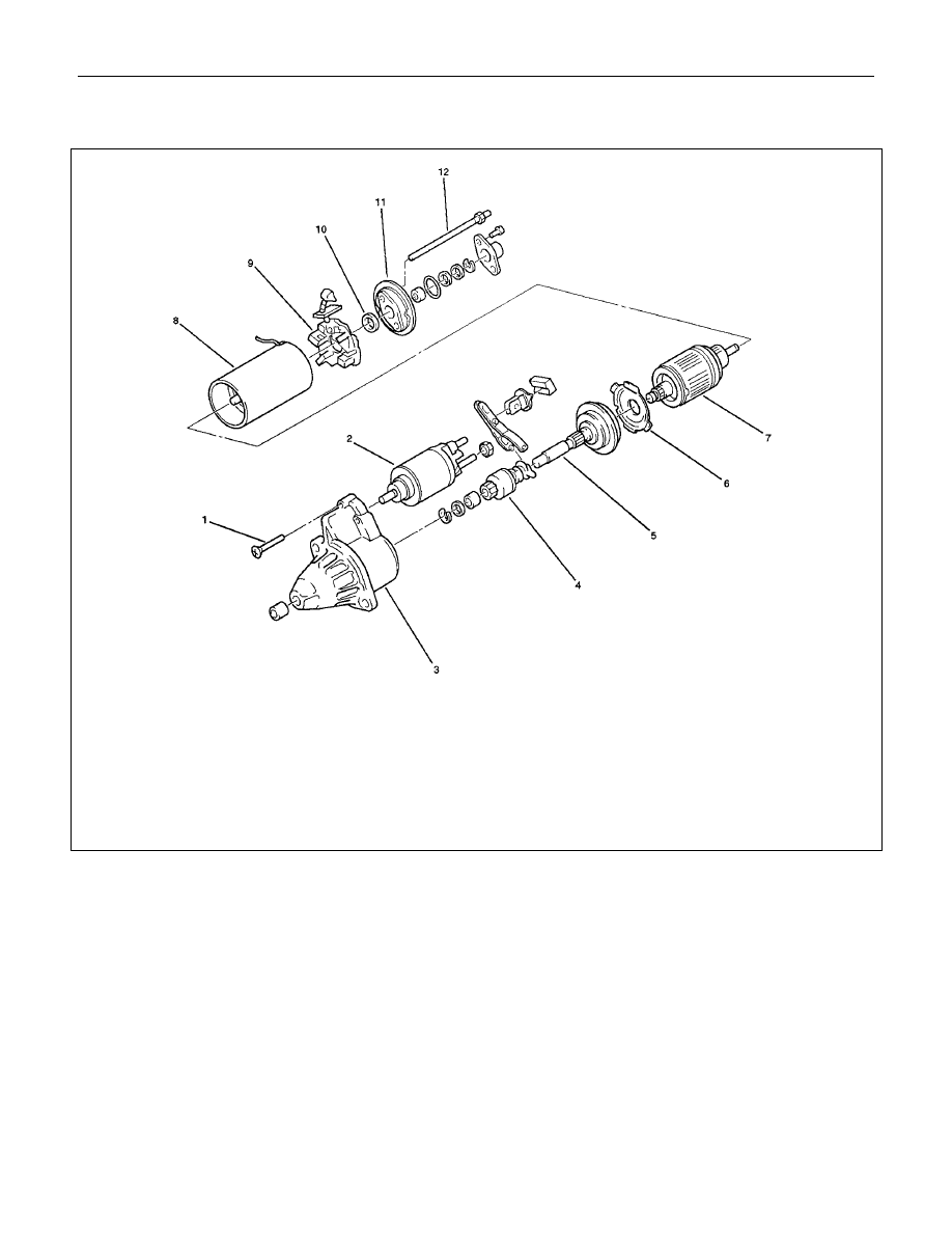
Disassembled View
Legend
1 Bolt
2 Magnetic Switch
3 Gear Case
4 Piston
5 Piston Shaft
6 Center Bracket
7 Armature
8 Yoke Assembly
9 Brush and Brush Holder
10 Washer
11 Rear Cover
12 Through Bolt
STARTING AND CHARGING SYSTEM 6D3-5
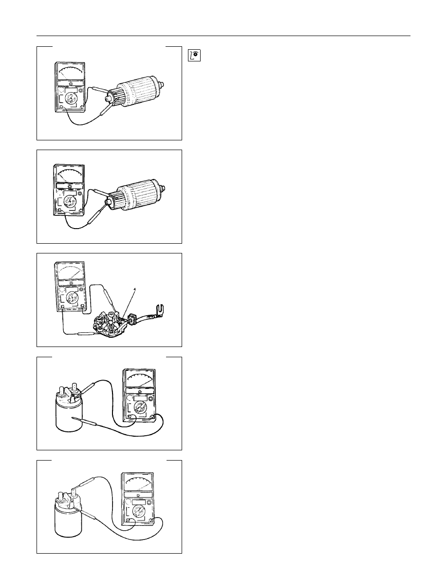
Inspection and Repair
Repair or replace necessary parts if extreme wear or damage
is found during inspection.
Armature
Check for continuity between commutator and segment.
Replace commutator if there is no continuity (i.e.,
disconnected).
Check for continuity between commutator and shaft.
Also, check for continuity between commutator and armature
core, armature core and shaft. Replace commutator if there is
continuity (i.e., internally grounded).
Brush
Measure the length of brush.
Replace with a new one, if it is below the limit.
Brush Holder
Check for continuity between brush holder (+) (4) and base (-).
Replace, if there is continuity (i.e., insulation is broken).
Magnetic Switch
Check for continuity of shunt coil between terminals S and M.
Replace, if there is no continuity (i.e., coil is disconnected).
Continuity of Series Coil
Check for continuity between terminals S and M.
Replace, if there is no continuity (i.e., coil is disconnected).
Нет комментариевНе стесняйтесь поделиться с нами вашим ценным мнением.
Текст