Isuzu D-Max / Isuzu Rodeo (TFR/TFS). Manual — part 67

4JA1-TC/4JH1-TC ENGINE DRIVEABILITY AND EMISSIONS
6E–263
9
Check any accessory parts which may cause electric
interference or magnetic interference.
Was the problem found?
—
Remove the
accessory parts
and verify repair
Go to Step 10
10
Is the ECM programmed with the latest software
release?
If not, download the latest software to the ECM using
the “SPS (Service Programming System)”.
Was the problem solved?
—
Verify repair
Go to Step 11
11
Substitute a known good ECM and recheck.
Was the problem solved?
IMPORTANT: The replacement ECM must be
programmed. Refer to section of the Service
Programming System (SPS) in this manual.
Following ECM programming, the immobiliser system
(if equipped) must be linked to the ECM. Refer to
section 11 “Immobiliser System-ECM replacement” for
the ECM/Immobiliser linking procedure.
—
Go to Step 12
Go to Step 13
12
Replace the ECM.
Is the action complete?
IMPORTANT: The replacement ECM must be
programmed. Refer to section of the Service
Programming System (SPS) in this manual.
Following ECM programming, the immobiliser system
(if equipped) must be linked to the ECM. Refer to
section 11 “Immobiliser System-ECM replacement” for
the ECM/Immobiliser linking procedure.
—
Verify repair
—
13
Replace the injection pump assembly.
Is the action complete?
—
Verify repair
—
Step
Action
Value(s)
Yes
No
6E–264
4JA1-TC/4JH1-TC ENGINE DRIVEABILITY AND EMISSIONS
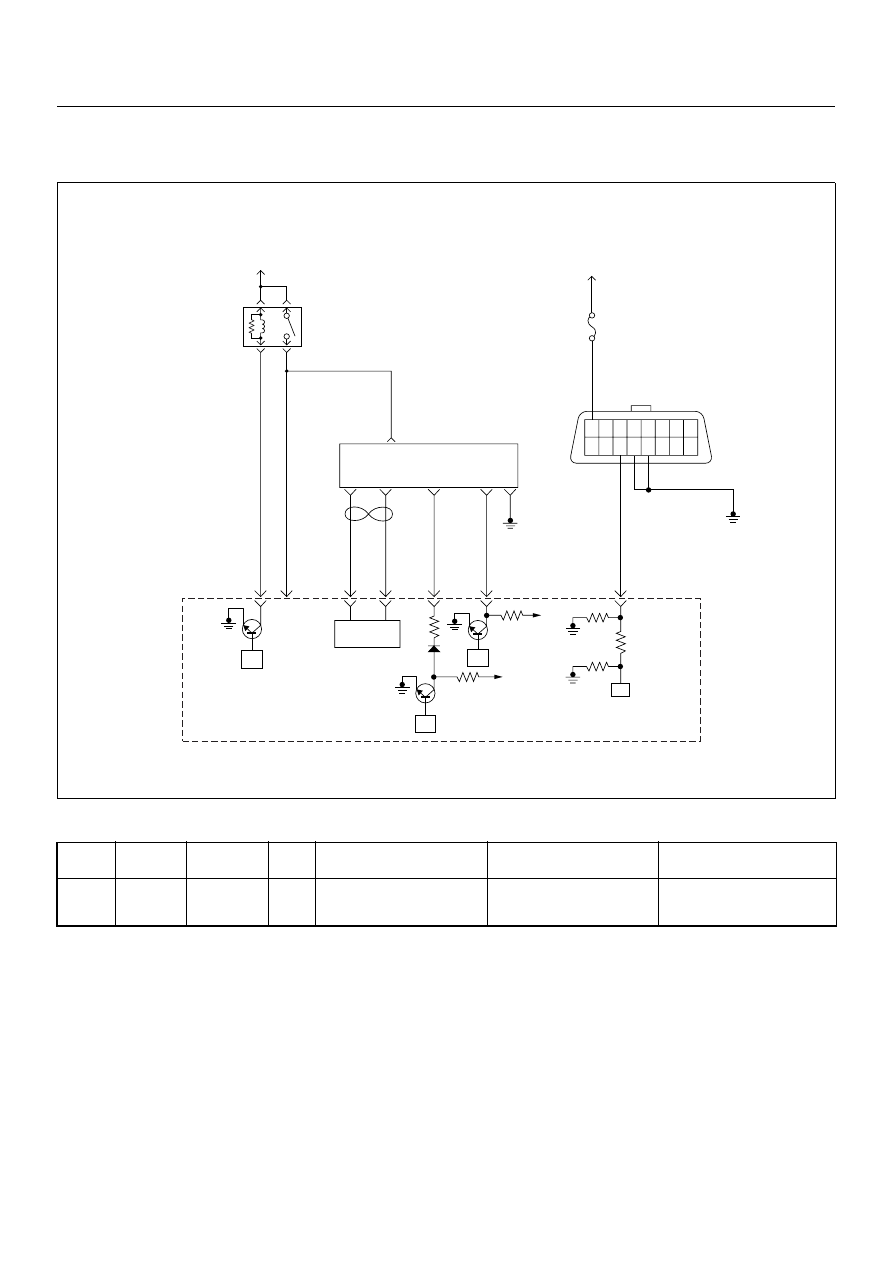
DIAGNOSTIC TROUBLE CODE (DTC) P1345 (SYMPTOM CODE A)
(FLASH CODE 45) CAMSHAFT SPEED MALFUNCTION
Condition for setting the DTC and action taken when the DTC sets
Circuit Description
The pump camshaft sensor is a magnet with a coil. It
uses to combine with the pulser. The pulser is attached
main shaft in the pump. It likes a gear shape.
The pump camshaft sensor is attached to the pump
control unit (PSG). The signal of pump camshaft speed
is sent via the CAN-bus from the PSG to ECM.
Diagnostic Aids
An intermittent may be caused by the following:
• Poor connections.
• Misrouted harness.
• Rubbed through wire insulation.
• Broken wire inside the insulation.
Check for the following conditions:
• Poor connection at ECM and PSG-Inspect harness
connectors for backed out terminals, improper
mating, broken locks, improperly formed or damaged
terminals, and poor terminal to wire connection.
• Damaged harness-Inspect the wiring harness for
damage. If the harness appears to be OK, observe
the “Pump Speed” display on the Tech2 while moving
connectors and wiring harnesses. A change in the
display will indicate the location of the fault.
Flash
Code
Code
Symptom
Code
MIL
DTC Name
DTC Setting Condition
Fail-Safe (Back Up)
45
P1345
A
ON
Camshaft Speed Malfunction
The PSG (pump control unit)
is recognized incorrect cam-
shaft speed signal.
No fail-safe function.
45
16 15 14 13 12 11 10 9
8 7 6 5 4 3 2 1
Battery
Voltage
Battery
Voltage
0.5
RED/
YEL
2.0
BLU/
RED
7
PSG(Pump Control Unit)
Injection
Pump
2
1
5
8
0.5
WHT
2.0
BLU/
RED
0.5
BLU/
BLK
0.5
RED
0.5
ORG
100
3
58
99
105
91
0.5
PNK
6
2.0
BLK
µP
CAN
Controller
Batt
Batt
IC
µP
0.5
BLU
Stop
Light
10A
1.25
BLK
µP
Engine
Control
Module
(ECM)
ECM
Main Relay

4JA1-TC/4JH1-TC ENGINE DRIVEABILITY AND EMISSIONS
6E–265
Diagnostic Trouble Code (DTC) P1345 (Symptom Code A) (Flash Code 45)
Camshaft Speed Malfunction
Step
Action
Value(s)
Yes
No
1
Was the “On-Board Diagnostic (OBD) System Check”
performed?
—
Go to Step 2
Go to On Board
Diagnostic
(OBD) System
Check
2
1. Connect the Tech 2.
2. Review and record the failure information.
3. Select “F0: Read DTC Infor As Stored By ECU” in
“F0: Diagnostic Trouble Codes”.
Is the DTC P1345 (Symptom Code A) stored as
“Present Failure”?
—
Go to Step 3
Refer to
Diagnostic Aids
and Go to Step
3
3
1. Using the Tech 2, ignition “On” and engine “Off”.
2. Select “F1: Clear DTC Information” in “F0:
Diagnostic Trouble Codes” with the Tech 2 and
clear the DTC information.
3. Operate the vehicle and monitor the “F0: Read
DTC Infor As Stored By ECU” in the “F0:
Diagnostic Trouble Codes”.
Was the DTC P1345 (Symptom Code A) stored in this
ignition cycle?
—
Go to Step 4
Refer to
Diagnostic Aids
and Go to Step
4
4
1. Using the Tech 2, ignition “On” and engine “Off”.
2. Monitor the “Pump Speed” in the data display.
Does the Tech 2 indicate correct “Pump Speed”
depending on engine speed?
—
Go to Step 6
Go to Step 5
5
Check any accessory parts which may cause electric
interference or magnetic interference.
Was the problem found?
—
Remove the
accessory parts
and verify repair
Go to Step 9
6
Is the ECM programmed with the latest software
release?
If not, download the latest software to the ECM using
the “SPS (Service Programming System)”.
Was the problem solved?
—
Verify repair
Go to Step 7
7
Substitute a known good ECM and recheck.
Was the problem solved?
IMPORTANT: The replacement ECM must be
programmed. Refer to section of the Service
Programming System (SPS) in this manual.
Following ECM programming, the immobiliser system
(if equipped) must be linked to the ECM. Refer to
section 11 “Immobiliser System-ECM replacement” for
the ECM/Immobiliser linking procedure.
—
Go to Step 8
Go to Step 9
8
Replace the ECM.
Is the action complete?
IMPORTANT: The replacement ECM must be
programmed. Refer to section of the Service
Programming System (SPS) in this manual.
Following ECM programming, the immobiliser system
(if equipped) must be linked to the ECM. Refer to
section 11 “Immobiliser System-ECM replacement” for
the ECM/Immobiliser linking procedure.
—
Verify repair
—
9
Replace the injection pump assembly.
Is the action complete?
—
Verify repair
—
6E–266
4JA1-TC/4JH1-TC ENGINE DRIVEABILITY AND EMISSIONS
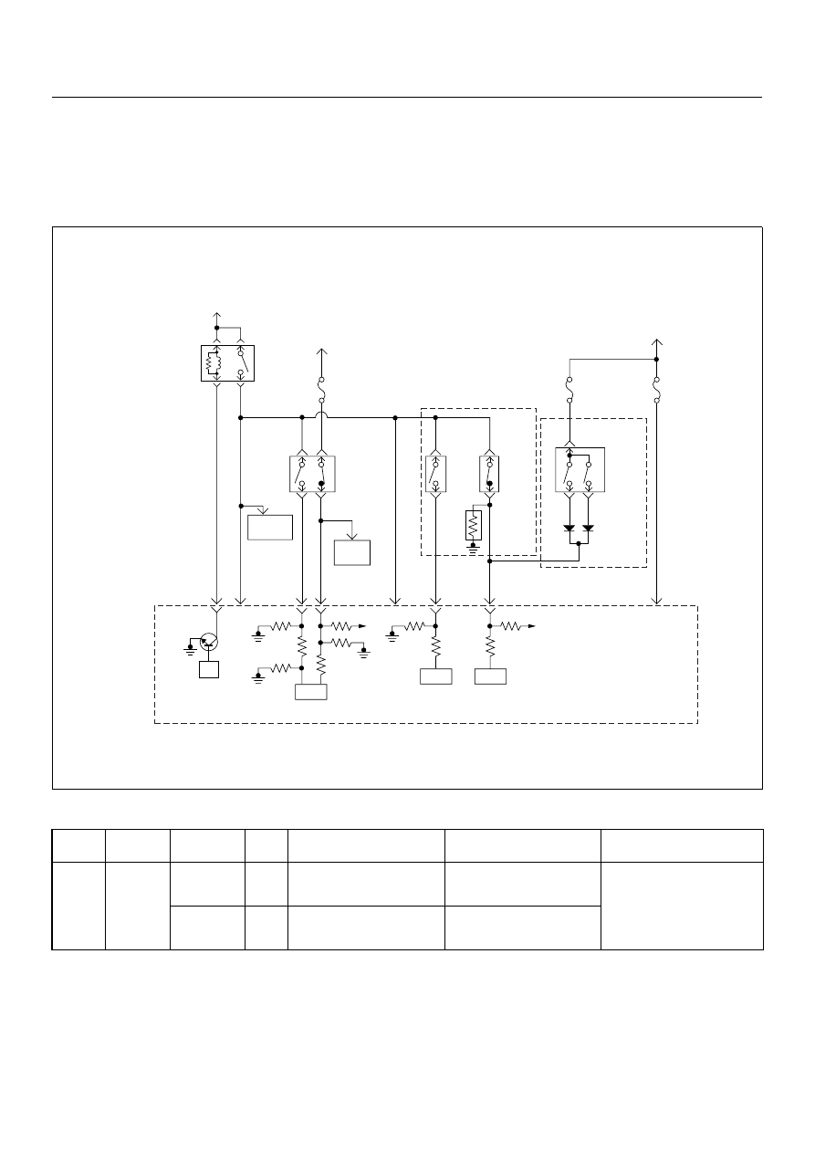
DIAGNOSTIC TROUBLE CODE (DTC) P1520 (SYMPTOM CODE A)
(FLASH CODE 47) NEUTRAL SWITCH ON ERROR
DIAGNOSTIC TROUBLE CODE (DTC) P1520 (SYMPTOM CODE B)
(FLASH CODE 47) NEUTRAL SWITCH OFF ERROR
Condition for setting the DTC and action taken when the DTC sets
Circuit Description
The ECM monitors the neutral switch (A/T: N or P
position switch in inhibitor switch) signal on the feed
terminal to the ECM. If the neutral switch with
malfunction, DTC P1520 (Symptom Code A) or P1520
(Symptom Code B) will be stored.
Diagnostic Aids
An intermittent may be caused by the following:
• Poor connections.
• Misrouted harness.
• Rubbed through wire insulation.
• Broken wire inside the insulation.
Flash
Code
Code
Symptom
Code
MIL
DTC Name
DTC Setting Condition
Fail-Safe (Back Up)
47
P1520
A
ON
Neutral Switch ON Error
Neutral switch signal is input-
ted “On” three times consecu-
tively under driving conditions.
No fail-safe function.
B
ON
Neutral Switch OFF Error
Neutral switch signal is input-
ted “Off” three times consecu-
tively under driving conditions.
Battery
Voltage
Battery
Voltage
ECM
Main Relay
Stop
Light
10A
Injection
Pump
Stop
Lamp
IC
IC
CPU
0.5
BLU/
BLK
58
2.0
BLU/
RED
0.5
BLU/
RED
3
0.5
WHT/
BLK
65
0.85
RED
0.85
RED
0.85
GRN
30
0.5
BLU/
RED
63
0.5
YEL
31
0.5
RED/
BLK
0.5
BLU/
RED
0.5
BLU/
RED
0.85
WHT
0.5
WHT/
RED
0.5
RED/
GRN
Clutch
SW
Resister
Neutral
SW
87
0.5
BLU/
YEL
39
Brake
SW
M/T
A/T
Inhibitor
SW
Ignition
SW
Back,
Turn
15A
Engine
15A
µP
N
P
Engine
Control
Module
(ECM)
Batt
Batt
Нет комментариевНе стесняйтесь поделиться с нами вашим ценным мнением.
Текст