Isuzu D-Max / Isuzu Rodeo (TFR/TFS). Manual — part 607
ENGINE ELECTRICAL 6D – 35
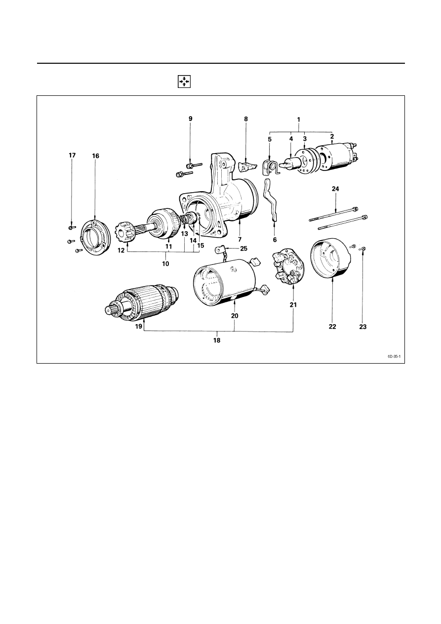
REASSEMBLY
Reassembly Steps
J
1. Magnetic switch assembly
14.
Pinion stopper
2. Magnetic switch
15.
Pinion stopper clip
3. Adjusting shims
16.
Bearing retainer
4. Plunger
17.
Screw
5. Torsion spring
18.
Motor assembly
6. Shift lever
19.
Armature
J
7. Gear case
20.
Yoke
J
8. Dust cover
J
21.
Brush holder
9. Bolt
22.
Rear
cover
J
10. Pinion assembly
23.
Screw
11. Clutch
J
24.
Through bolt
12. Pinion shaft
J
25.
Lead wire
13. Rerurn spring
6D – 36 ENGINE ELECTRICAL
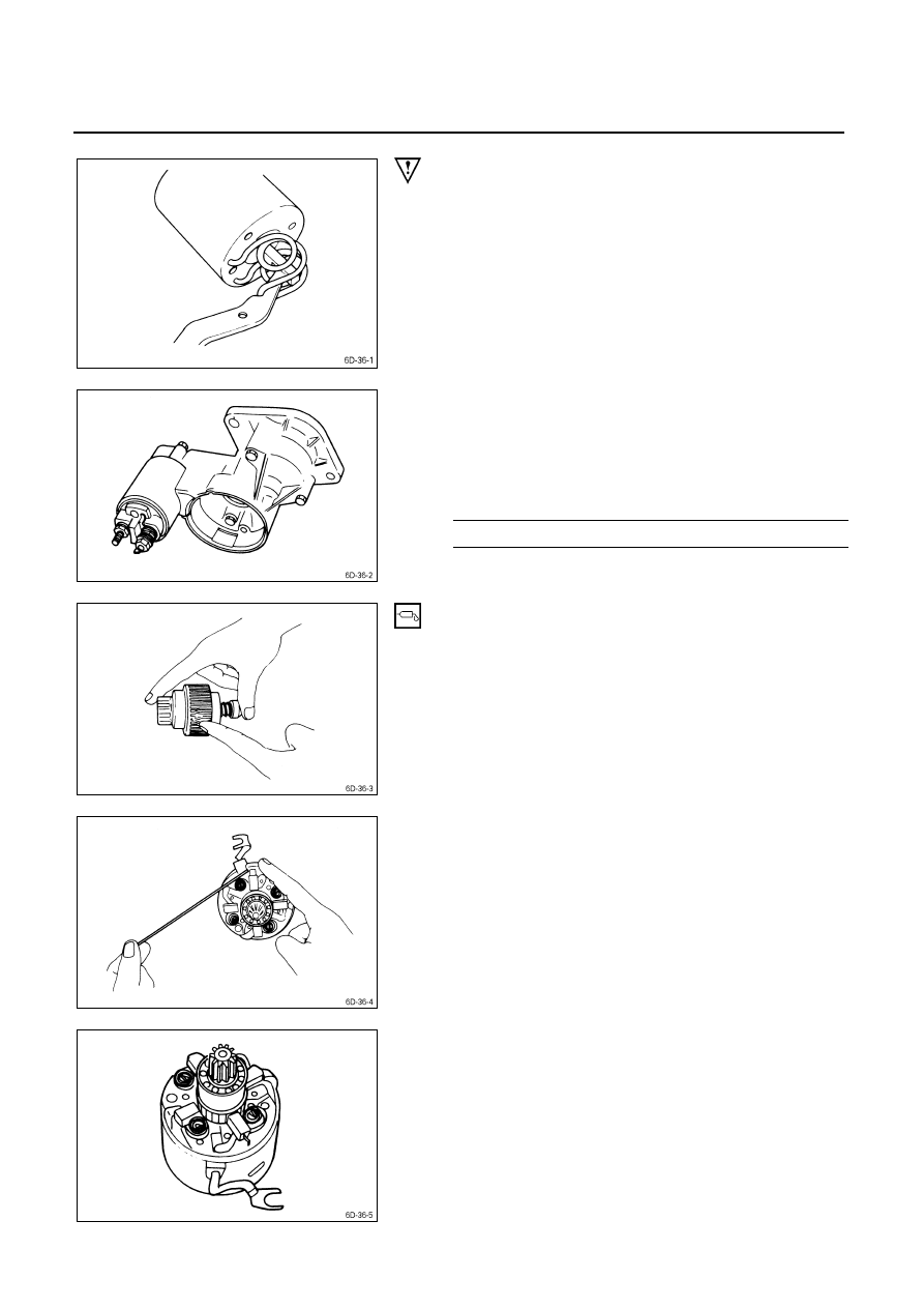
Important Operations
1. Magnetic Switch Assembly
1. Attach the torsion spring to the hole in the magnetic
switch as illustrated.
2. Insert the shift lever into the plunger hole of the
magnetic switch.
7. Gear
Case
8. Dust
Cover
1. Install the magnetic switch assembly in the gear case.
2. Install the dust cover.
Dust Cover Bolt Torque
kg
⋅m(lb⋅ft/N⋅m)
0.75
± 0.5 (5.4 ± 3.6/7.4 ± 5)
10. Pinion Assembly
Apply a coat of grease to the reduction gear and install the
pinion assembly to the armature shaft.
21. Brush Holders
1. Install the brushes into the brush holder with raising
the spring end of the brush spring.
Take care not to damage the commutator face.
2. Install the brush holder with aligning the peripheries of
the yoke and the brush holder.
ENGINE ELECTRICAL 6D – 37
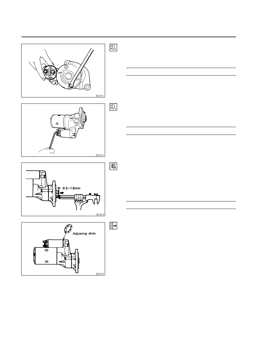
24. Through Bolt
Install the through bolts in the rear cover and tighten them
to the specified torque.
Through Bolt Torque
kg
⋅m(lb⋅ft/N⋅m)
0.6
± 0.1 (4.3 ± 0.7/5.9 ± 1.0)
25. Lead Wire
Connect the lead wire in the magnetic switch and tighten
the terminal nut to the specified torque.
Lead Wire Terminal Nut Torque
kg
⋅m(lb⋅ft)
0.8
± 0.1 (5.8 ± 0.7/7.8 ± 1.0)
Inspection After Assembly
Use a vernier caliper to measure the pinion shaft thrust
play.
The pinion shaft thrust play is equal to the pinion shaft end
and pinion stopper clearance.
Pinion Shaft Thrust Play
mm (in)
0.3 - 1.5 (0.01 – 0.06)
In a case where the pinion gap outside the
specified value;
Make an adjustment using a shim(s).
Adjusting shims are available in 0.5 mm and 0.8 mm (0.02 and
0.03 in.) sizes.
6D – 38 ENGINE ELECTRICAL
PRE-HEATING SYSTEM
INSPECTION AND REPAIR
Make the necessary adjustments, repairs, and part replacement if excessive wear or damage is discovered during
inspection.
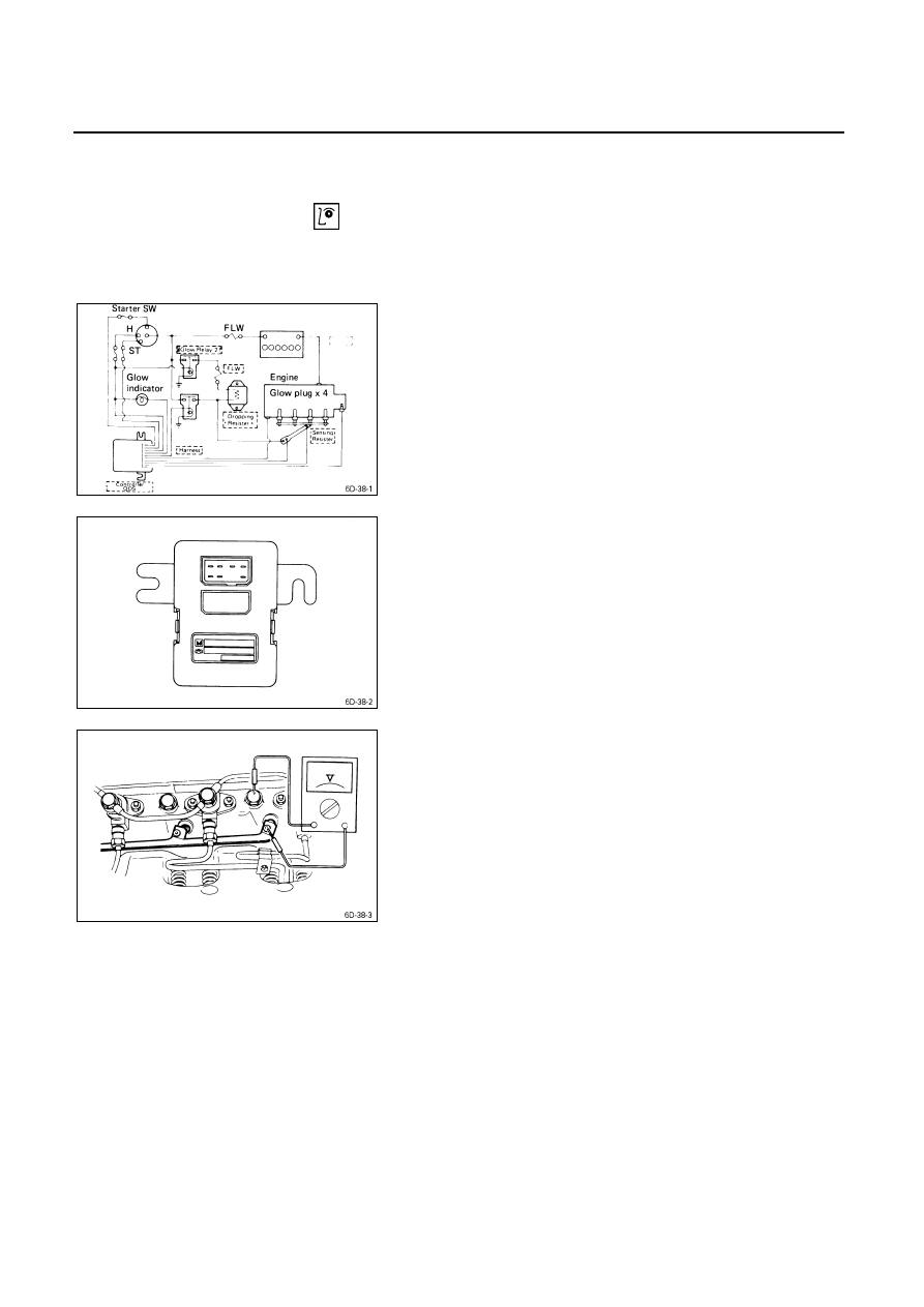
SYSTEM CIRCUIT
Visual Check
Check the main fuses and the glow indicator for damage.
Replace the part(s) if required.
GLOW TIMER
The glow timer is initially activated by the starter switch.
Thereafter, signals from the thermoswitch reach the glow
timer to control the glow plug relay operation time.
The thermoswitch and timer unit also act to protect the
battery in the event the starter key is engaged for an
excessively long time.
Glow Timer Operation
1. Disconnect the lead wires at the thermoswitch.
2. Connect a voltmeter between the glow plug and
ground.
3. Turn the starter switch from “OFF” to “ON”.
The engine must be stopped.
4. Note the time the glow indicator remains on.
If the glow indicator remains on for approximately 1~6
seconds (4JG2T Engine model) or 3.5 seconds (4JA1,
4JB1T Engine model), the glow timer “ON” time is
normal.
If the glow indicator does not remain on for
approximately 1~6 seconds or 3.5 seconds, trouble in
the glow timer or, the glow relay, is indicated.
5. Return the starter switch to “OFF”.
Нет комментариевНе стесняйтесь поделиться с нами вашим ценным мнением.
Текст