Isuzu D-Max / Isuzu Rodeo (TFR/TFS). Manual — part 568
6A – 110 ENGINE MECHANICAL
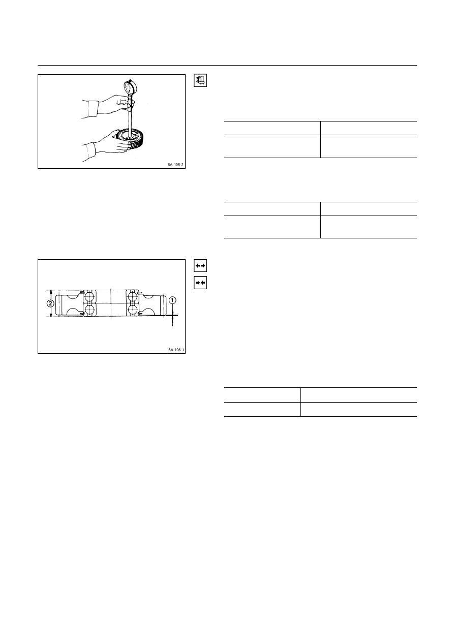
Idler Gear “A” Shaft inside Diameter
1. Use an inside dial indicator or an inside micrometer to
measure the idler gear inside diameter.
Idler Gear Inside Diameter
mm (in)
Standard Limit
45.0 – 45.03
(1.7717 – 1.7718)
45.10 (1.7756)
If the clearance between the idler gear shaft outside
diameter and the idler gear inside diameter exceeds the
limit, the idler gear must be replaced.
Idler Gear Shaft and Idler Gear Clearance
mm (in)
Standard Limit
0.025 – 0.085
(0.0010 – 0.0033)
0.200 (0.008)
Idler Gear “B”
Bearing Replacement
Bearing Removal
Use a bench press or a hammer and a bar to remove the
bearing from the idler gear.
Bearing Installation
Use a bench press and bar to install the bearing into the
idler gear.
Bearing Projection and Height
mm (in)
Projection
Q
0.4 – 0.6 (0.016 – 0.024)
Height
R
23.7 – 24.0 (0.933 – 0.945)
Note:
The bench press and bar should make contact only
with the bearing outer races. Do not allow them to
make contact with the bearing inner races.
Bearing damage and reduced bearing service life will
result.

ENGINE MECHANICAL 6A – 111
TIMING GEAR CASE COVER
Replace the crankshaft front oil seal if it is excessively
worn or damaged.
Crankshaft Front Oil Seal Replacement
Oil Seal Removal
Use a plastic hammer and a screwdriver to tap around the
oil seal to free it from the gear case cover.
Take care not to damage the oil seal lip surfaces.
Oil Seal Installation
Use the installer to install the front oil seal
Q
to the gear
case cover
R
.
Oil Seal Installer: 5-8840-2061-0
Note the oil seal installation depth
S
shown in the
illustration.
Depth
S
= 1 mm (0.039 in.)
6A – 112 ENGINE MECHANICAL
REASSEMBLY
INTERNAL PARTS
MINOR COMPONENTS
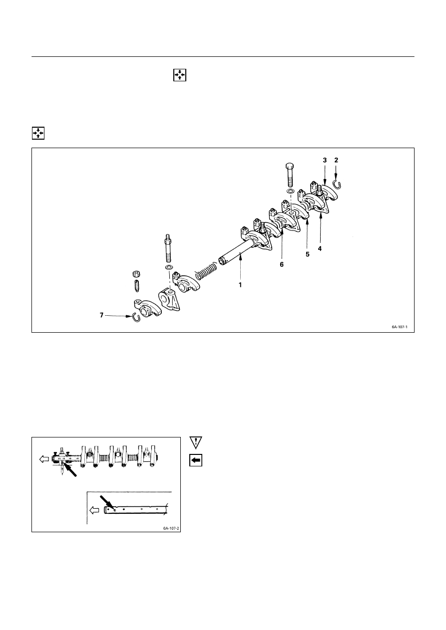
ROCKER ARM SHAFT AND ROCKER ARM
Reassembly Steps
t
1.
Rocker arm shaft
5.
Rocker arm
2.
Rocker arm shaft snap ring
6.
Rocker arm shaft spring
3.
Rocker arm
7.
Rocker arm shaft snap ring
4.
Rocker arm shaft bracket
Important Operations
1. Rocker Arm Shaft
1) Position the rocker arm shaft with the large oil hole
(4
φ
) facing the front of the engine.
2) Install the rocker arm shaft together with the rocker
arm, the rocker arm shaft bracket, and the spring.
ENGINE MECHANICAL 6A – 113
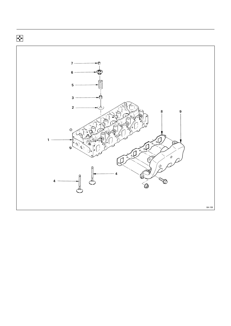
CYLINDER HEAD
Reassembly Steps
1.
Cylinder head
6.
Valve spring upper seat
2.
Valve spring lower seat
t
7.
Split collar
t
3.
Valve stem oil seal
t
8.
Intake manifold gasket
t
4.
Intake and exhaust valve
t
9.
Intake manifold
t
5.
Valve spring
Нет комментариевНе стесняйтесь поделиться с нами вашим ценным мнением.
Текст