Isuzu D-Max / Isuzu Rodeo (TFR/TFS). Manual — part 566
6A – 102 ENGINE MECHANICAL
FLYWHEEL AND RING GEAR
Flywheel
1. Inspect the flywheel friction surface for excessive wear
and heat cracks.
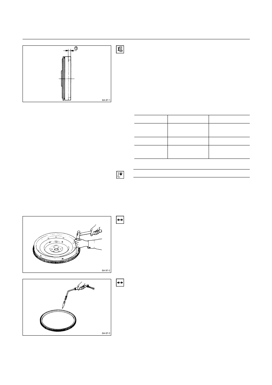
2. Measure the flywheel friction surface depth.
If the measured value is within the specified limit, the
flywheel may be reground.
If the measured value exceeds the specified limit, the
flywheel must be replaced.
Flywheel Friction Surface Depth
Q
mm
(in)
Standard
Limit
4JA1, 4JA1T,
4JA1TC
20 (0.787)
21 (0.827)
4JB1T 14
(0.551)
15
(0.591)
4JG2T,
4JH1TC
18 (0.708)
19 (0.748)
Flywheel Friction Surface Roughness
mm (in)
Less than 0.006 (0.00024)
Ring Gear
Inspect the ring gear.
If the ring gear teeth are broken or excessively worn, the
ring gear must be replaced.
Ring Gear Replacement
Ring Gear Removal
Strike around the edges of the ring gear with a hammer
and chisel to remove it.
Ring Gear Installation
1. Heat the ring gear evenly with a gas burner to invite
thermal expansion.
Do not allow the temperature of the gas burner to
exceed 200
°C (390°F).
2. Install the ring gear when it is sufficiently heated.
The ring gear must be installed with the chamfer
facing the clutch.
ENGINE MECHANICAL 6A – 103
PISTON
Piston Grade Selection and Cylinder Bore
Measurement
Refer to the Section “CYLINDER BODY”, Item “Cylinder
Liner Bore Measurement” for details on piston grade
selection and cylinder liner bore measurement.
PISTON RING
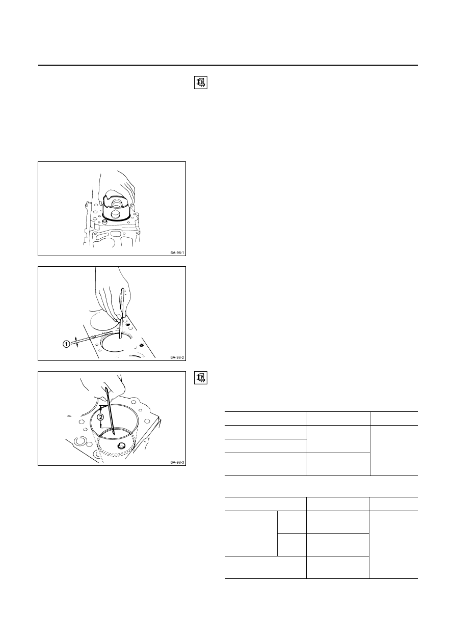
Piston Ring Gap
1. Insert the piston ring horizontally (in the position it
would assume if it were installed to the piston) into the
cylinder liner.
2. Push the piston ring into the cylinder bore until it
reaches the measuring point
Q
or
R
where the
cylinder liner bore is the smallest.
Do not allow the piston ring to slant to one side or the
other. It must be perfectly horizontal.
Measuring Point
Q
10 mm (0.4 in)
or
Measuring Point
R
120 mm (4.7 in)
3. Use a feeler gauge to measure the piston ring gap.
If the measured value exceeds the specified limit, the
piston ring must be replaced.
Piston Ring Gap
mm (in)
Standard
Limit
1st Compression Ring
2nd Compression Ring
0.2 – 0.4
(0.008 – 0.016)
Oil Ring
0.1 – 0.3
(0.004 – 0.012)
1.5
(0.059)
4JG2
mm (in)
Standard Limit
1st
0.20 – 0.35
(0.0079 – 0.0138)
Compression
ring
2nd
0.37 – 0.52
(0.0146 – 0.0205)
Oil ring
0.20 – 0.40
(0.0079 – 0.0157)
1.5
(0.059)
6A – 104 ENGINE MECHANICAL
4JH1TC
mm (in)
Standard Limit
1st
0.30 – 0.50
(0.0118 – 0.0197)
Compression
ring
2nd
0.30 – 0.50
(0.0118 – 0.0197)
Oil ring
0.25 – 0.45
(0.0098 – 0.0117)
0.15
(0.0059)
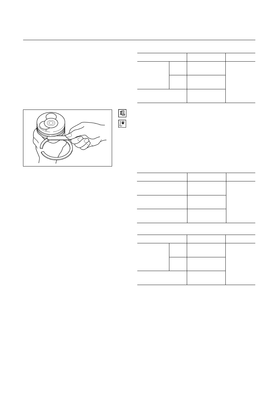
Piston Ring and Piston Ring Groove Clearance
Use a feeler gauge to measure the clearance between the
piston ring and the piston ring groove at several points
around the piston.
If the clearance between the piston ring and the piston ring
groove exceeds the specified limit, the piston ring must be
replaced.
Piston Ring and Piston Ring Groove
Clearance
4JA1, 4JB1T, 4JA1T, 4JA1TC mm (in)
Standard
Limit
1st Compression Ring
0.09 – 0.125
(0.0035 – 0.0049)
2nd Compression Ring
0.05 – 0.085
(0.002 – 0.0033)
Oil Ring
0.03 – 0.070
(0.0012 – 0.0028)
0.15
(0.0059)
4JG2, 4JH1TC mm (in)
Standard Limit
1st
0.09 – 0.13
(0.0035 – 0.0051)
Compression
ring
2nd
0.05 – 0.09
(0.0020 – 0.0035)
Oil ring
0.03 – 0.07
(0.0012 – 0.0028)
0.15
(0.0059)
4. Visually inspect the piston rings.
If a piston ring groove is damaged or distorted, the
piston must be replaced.
015RY00029
ENGINE MECHANICAL 6A – 105
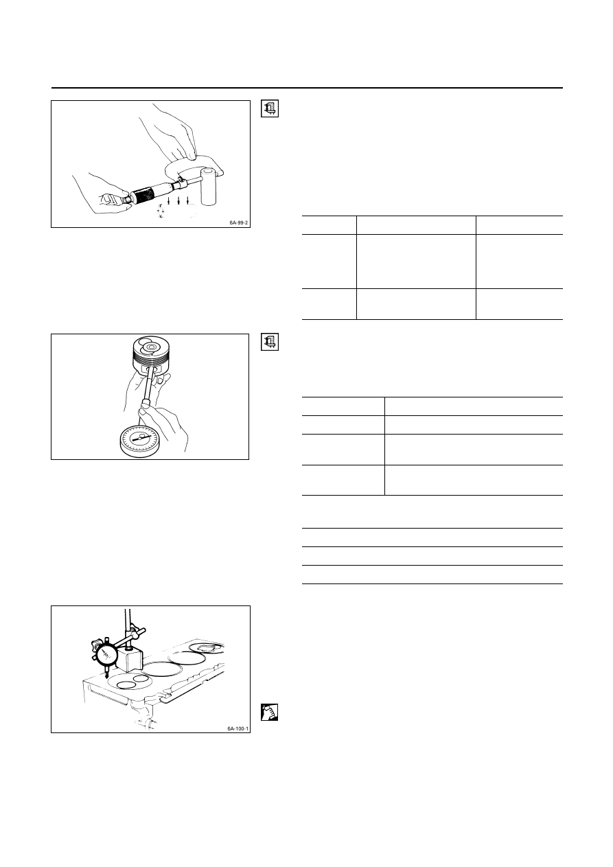
PISTON PIN
Piston Pin Diameter
Use a micrometer to measure the piston pin diameter at
several points.
If the measured value is less than the specified limit, the
piston pin must be replaced.
Piston Pin Diameter
mm (in)
Standard Limit
4JA1
4JA1T
4JA1TC
4JH1TC
30.995 – 31.000
(1.2202 – 1.2204)
30.97 (1.219)
4JB1T
4JG2T
33.994 – 34.000
(1.3383 – 1.3386)
33.97 (1.337)
Piston Pin and Piston Clearance
Use and inside dial indicator to measure the piston pin
hole (in the piston).
Piston Pin Hold
mm (in)
Standard
4JA1, 4JA1T
31.002 – 31.010 (1.2206 – 1.2208)
4JB1T
4JG2T
34.002 – 34.010 (1.3387 – 1.3390)
(1.3383 – 1.3386)
4JA1TC
4JH1TC
31.005 – 31.013 (1.2207 – 1.2210)
Piston Pin and Piston Pin Hole Clearance
mm (in)
0.002 – 0.015 (0.00008 – 0.0006)
4JA1TC, 4JH1TC
0.005 – 0.018 (0.00019 – 0.0007)
CYLINDER HEAD GASKET SELECTION
Cylinder head gasket is determined by the piston head
projection from the cylinder body upper surface, in order to
improve engine performance.
Three types of gasket are provided by the difference of
thickness. Select the adequet one out of three grades of
gasket, according to the following procedure.
Before measurement, clear off carbon from the piston
head and cylinder body surface and also clean the place
where a gasket was installed.
015RY00030
Нет комментариевНе стесняйтесь поделиться с нами вашим ценным мнением.
Текст