Isuzu D-Max / Isuzu Rodeo (TFR/TFS). Manual — part 1780

ON-VEHICLE SERVICE (JR405E) 7A3-9
POWER AND 3RD START SWITCH
Inspect
1. Block the wheels.
2. Disconnect the negative battery cable.
3. Pry out the switch from the floor console.
4. Disconnect the harness connector.
5. Check continuity between terminal (5) and (6) at third
(3rd) position.
6. Check continuity between terminals (3) and (6) at
power (PWR) position.
7. Replace the power and 3rd start switch when the
result of inspection is found abnormal.
8. Connect the harness connector.
9. Connect the negative battery cable.
10. Remove the wheel blocks.
238R300003

7A3-10 ON-VEHICLE SERVICE (JR405E)
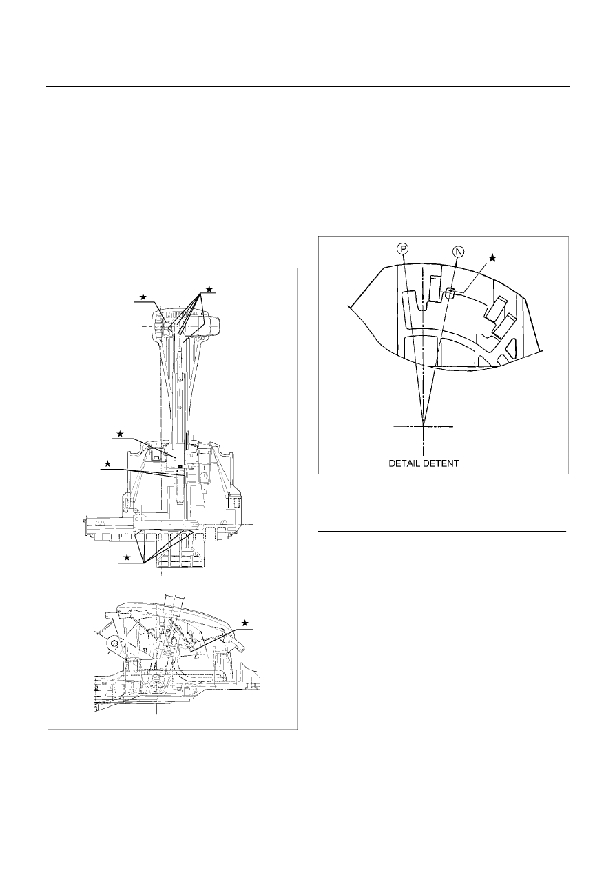
SELECT LEVER
RTW37ALF001101
Legend
1. Rear console
2. Front console
3. Select lever knob
4. Upper housing
5 Lamp
assembly
6 Base
plate
7 Grooved
pin
8 Spring
plate
9 Lever
assembly
10 Sleeve
Remove or Disconnect
1. Block the wheels.
2. Disconnect the negative battery cable.
3. Remove the rear console and the front console.
4. Remove the 2 screws fixing the select lever knob.
5. Remove the knob together with the knob button and
spring from the lever.
6. Turn the sleeve counterclockwise to remove it. Make
a note of the number of turns required to free the
sleeve.
7. Remove the harness connectors from the base plate.
8. Remove the upper housing (held in place by 4
latched fasteners).
9. Remove the spring plate.
ON-VEHICLE SERVICE (JR405E) 7A3-11
10. Remove the grooved pin.
11.
Remove the lever assembly by pressing the rod
down (lever in N position).
12.
If lamp replacement is required, remove the lamp
assembly from the lamp socket (align the socket
grooved portion and the lamp assembly protruding
portion).
Install or Connect
NOTE
Apply MULTEMP No. 2 grease (or equivalent) to the
select lever. Refer to the illustration.
RTW37ALH000201
1. Install the lever assembly to the base plate.
a. Insert and secure shaft.
b. Insert pawled end of shaft into base plate hole.
c. Insert grooved pin of shaft into detente aperture
(lever assembly in N position).
2.Install the spring plate.
a. Insert the grooved pin into the base plate detente
groove until it touches the front wall (lever
assembly in N position).
RTW37ASH001001
b. Stack the short spring plate tighten the screws to
the specified torque.
Screw torque
2 N
⋅
m (0.2kg
⋅
m/17 lb ft)
c. Check that the grooved pin moves smoothly in
the detente groove (shift knob temporarily
installed).
3. Temporarily install the sleeve.
4. Install the lamp assembly to the lamp socket (if
removed at disassembly).
a. Align the recessed portion of the lamp socket with
the protruding portion of the lamp assembly.
b. Insert the lamp assembly into the lamp socket
and rotate it 90 degrees clockwise.
5. Attach the harness connectors to the base plate.
6. Move the lever to the “P” position.
7. Install the sleeve (rotate the sleeve clockwise the
same number of turns it was rotated
counterclockwise at disassembly).
8. Install the knob, the knob button, and the knob
spring.
7A3-12 ON-VEHICLE SERVICE (JR405E)
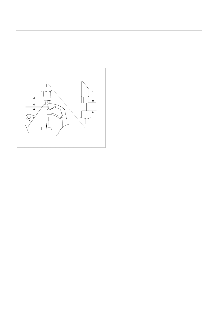
9. Adjust the clearance (2) between the detente plate
and the pin by moving the select lever knob sleeve
(1).
Detente plate and pin clearance
mm(in)
0.2 - 1.0 (0.01 - 0.04)
255R300002
10. Install the 2 screws securing the knob and tighten
them to the specified torque.
Screw torque: 2 N
⋅
m (0.2kg
⋅
m/17 lb in)
11.
Install the upper housing. Make sure that the 4
latched fasteners are securely closed.
Нет комментариевНе стесняйтесь поделиться с нами вашим ценным мнением.
Текст