Isuzu D-Max / Isuzu Rodeo (TFR/TFS). Manual — part 1781
ON-VEHICLE SERVICE (JR405E) 7A3-13
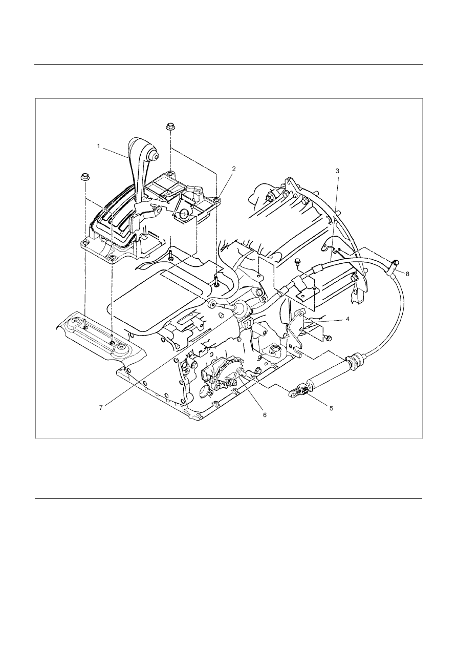
SHIFT CABLE
RTW37ALF001201
Legend
1. Select lever
2. Select lever base
3. Shift cable
4. Bracket
5. Adjuster
6. Manual shaft select lever
7. Shift cable retaining pawl
8. Clip
Remove or Disconnect
1. Block the wheels.
2. Disconnect the negative battery cable.
3. Move the select lever to the “N” position.
4. Remove the rear console and front console.
5. Disconnect the shift cable from the select lever.
6. Press on the shift cable retaining pawl to remove the
cable from the select lever base.
7. Disconnect the shift cable from the transmission
side.
8. Remove the shift cable from the bracket.
9. Pull the shift cable free from the bottom of the
vehicle.
7A3-14 ON-VEHICLE SERVICE (JR405E)
Install or Connect
1. Install the shift cable toward the inside of the cabin
from the bottom of the vehicle.
2. Push the shift cable into the select lever base.
3. Connect the shift cable to the select lever.
4. Fix the shift cable to the bracket.
Install the clip on the marking of shift cable.
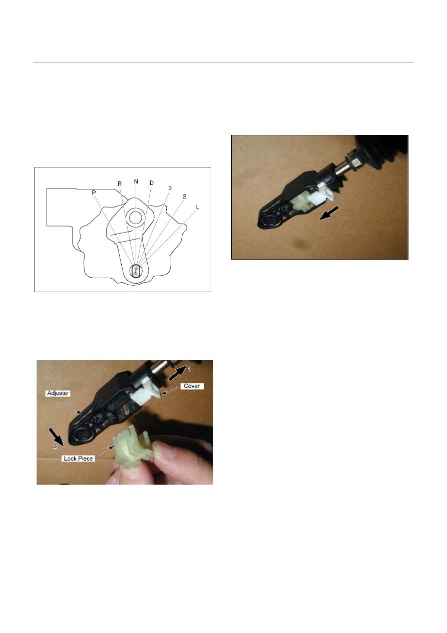
5. Check that the select lever is in the “N” position.
6. Check that the transmission is in the “N” position.
249R300002
7. Slide the cover in the direction shown by the arrow
(1).
8. Use an ordinary screwdriver to move the lock piece
from the position indicated by the arrow (2). Continue
to move the lock piece until the adjuster position
begins to change.
P1010012
9. Connect the shift cable to the manual shaft select
lever at the transmission side.
10.
Insert the lock piece to the adjuster (cable length
adjustment).
11.
Slide the cover on the adjuster and secure lock
piece.
P1010016-2
11. Press the select lever knob button 5 times.
Then check that the select lever moves smoothly to
each of its positions.
13. Check that the shift position indicated by the select
lever and the actual shift position are the same.
14. Install the front console and rear console.
15. Connect the negative battery cable.
16. Remove the wheel blocks.
ON-VEHICLE SERVICE (JR405E) 7A3-15
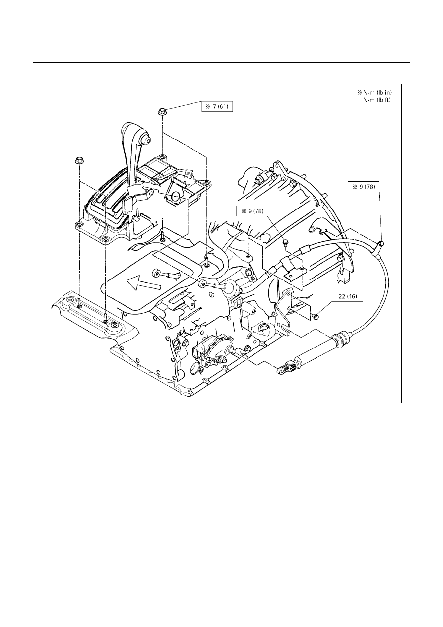
Torque Specifications
E07R300015
7A3-16 ON-VEHICLE SERVICE (JR405E)
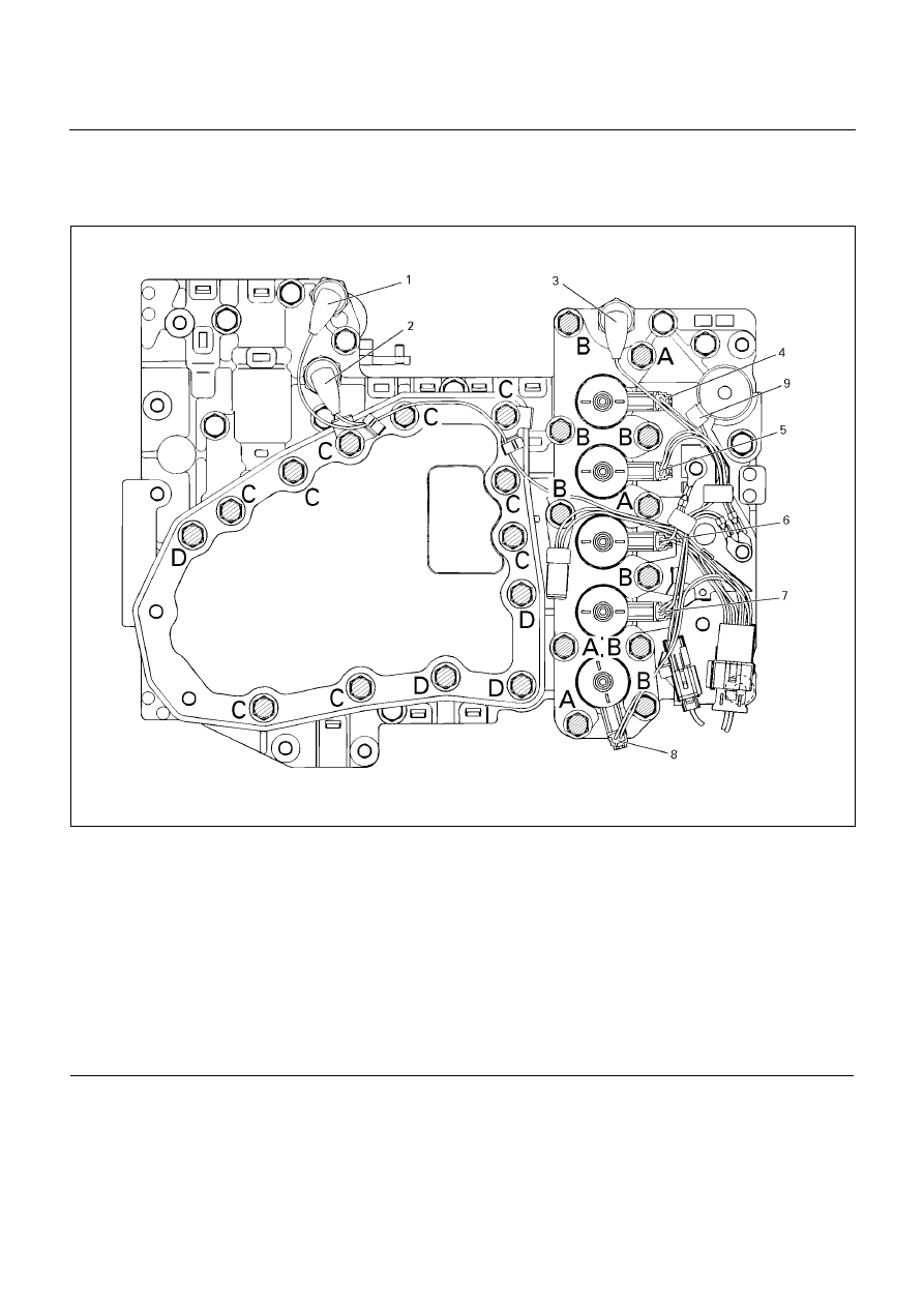
SOLENOIDS, OIL PRESSURE SWITCH AND OIL TEMPERATURE
SENSOR
244L300003
Legend
1. High clutch oil pressure switch connector
(wire color: Gray)
2. 2-4 brake oil pressure switch connector
(wire color: Brown)
3. Low and reverse brake oil pressure switch connector
(wire color: White)
4. Low and reverse brake duty solenoid connector
(wire color: Pink and White)
5. High clutch duty solenoid connector
(wire color: Green and Gray)
6. Lock-up duty solenoid connector
(wire color: Yellow and Black)
7. 2-4 brake duty solenoid connector
(wire color: Blue and Brown)
8. Low clutch duty solenoid connector
(wire color: Orange and Black)
9. Line pressure solenoid connector
(wire color: Pink)
Нет комментариевНе стесняйтесь поделиться с нами вашим ценным мнением.
Текст