Isuzu D-Max / Isuzu Rodeo (TFR/TFS). Manual — part 846
6E–113
3.2L ENGINE DRIVEABILITY AND EMISSIONS
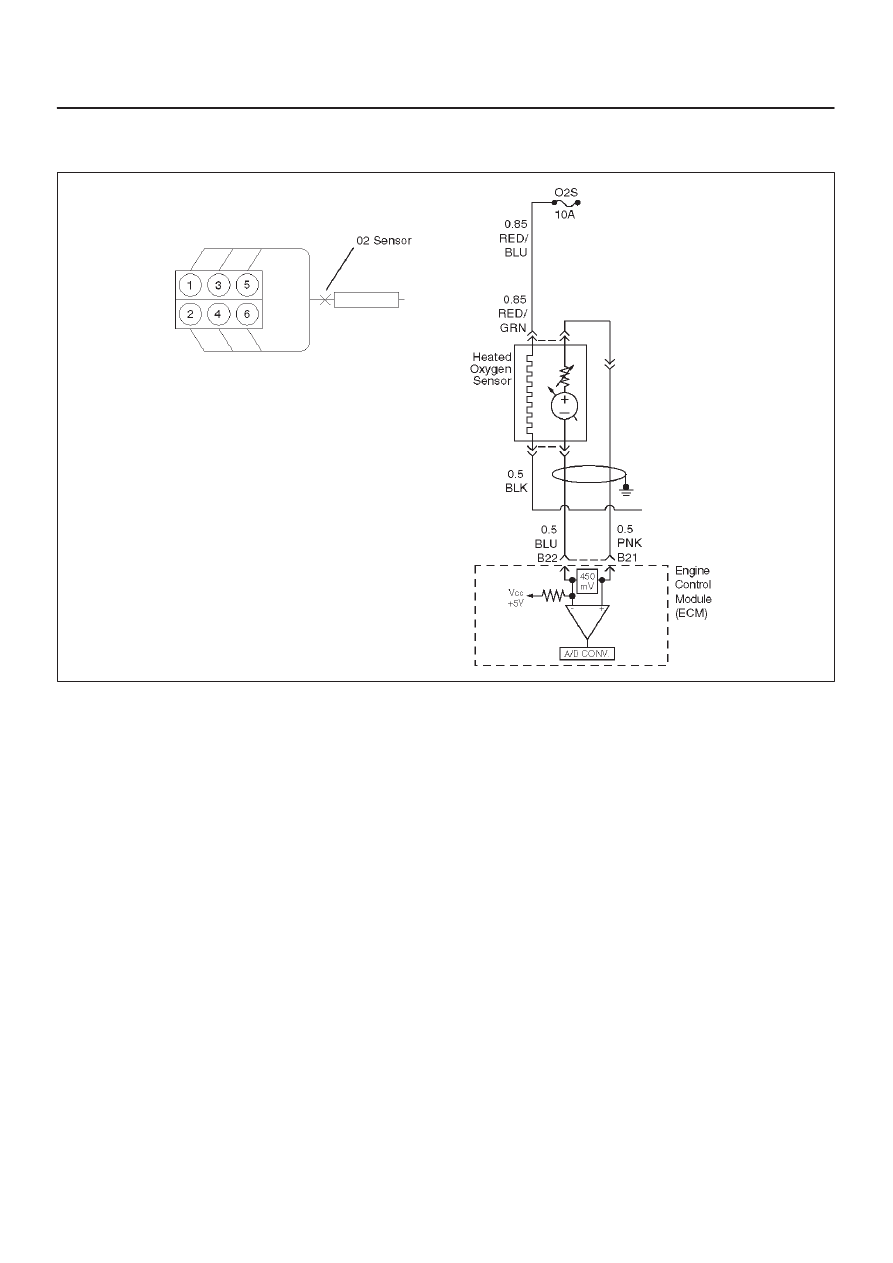
Diagnostic Trouble Code (DTC) P0131 (Flash DTC=15) HO2S Circuit Low
Voltage
060RW054
Circuit Description
The Engine Control Module ECM supplies a bias voltage
of about 450 mV between the heated oxygen sensor
(HO2S) signal high and signal low circuits. When
measured with a 10 megaohm digital voltmeter, this may
display as low as 350 mV. The oxygen sensor varies the
voltage within a range of about 1000 mV when the
exhaust is rich, down through about 10 mV when exhaust
is lean. The ECM constantly monitors the HO2S signal
during “closed loop” operation and compensates for a rich
or lean condition by decreasing or increasing injector
pulse width as necessary. If HO2S voltage remains
excessively low for an extended period of time, DTC
P0131 will be set.
Conditions for Setting the DTC
D
No related DTCs.
D
Vehicle is operating in “closed loop.”
D
Engine coolant temperature is between 70
°
C and
110
°
C.
D
Throttle angle is between 3% and 19%.
D
Vehicle speed is between 0Km/H and 120Km/H.
D
Throttle angle voltage change reading is below 0.3m
volts.
D
The O
2
sensor voltage more than 400m volts for 50
second.
Action Taken When the DTC Sets
D
The ECM will illuminate the malfunction indicator lamp
(MIL) the first time the fault is detected.
D
The ECM will store conditions which were present
when the DTC was set as Freeze Frame and in the
Failure Records data.
D
“Open loop” fuel control will be in effect.
Conditions for Clearing the MIL/DTC
D
The ECM will turn the MIL “OFF” on the third
consecutive trip cycle during which the diagnostic has
been run and the fault condition is no longer present.
D
A history DTC P0131 will clear after 40 consecutive
warm-up cycles have occurred without a fault.
D
DTC P0131 can be cleared by using the Tech 2 “Clear
Info” function or by disconnecting the ECM battery
feed.
Diagnostic Aids
Check for the following conditions:
D
Heated oxygen sensor wiring – The sensor pigtail may
be routed incorrectly and contacting the exhaust
system.
D
Poor ECM to engine block grounds.
D
Fuel pressure – The system will go lean if pressure is
too low. The ECM can compensate for some
decrease. However, If fuel pressure is too low, a DTC
P0131 may be set. Refer to
Fuel System Diagnosis.
D
Lean injector(s) – Perform “Injector Balance Test.”
6E–114
3.2L ENGINE DRIVEABILITY AND EMISSIONS
D
Exhaust leaks – An exhaust leak may cause outside air
to be pulled into the exhaust gas stream past the
HO2S, causing the system to appear lean. Check for
exhaust leaks that may cause a false lean condition to
be indicated.
D
MAF sensor – The system can go lean if the MAF
sensor signal indicates an engine airflow
measurement that is not correct. Disconnect the MAF
sensor to see if the lean condition is corrected. If so,
replace the MAF sensor.
D
Fuel contamination – Water, even in small amounts,
can be delivered to the fuel injectors. The water can
cause a lean exhaust to be indicated. Excessive
alcohol in the fuel can also cause this condition. Refer
to
Fuel System Diagnosis for the procedure to check
for fuel contamination.
D
If none of the above conditions are present, replace the
affected HO2S.
Test Description
Number(s) below refer to step numbers on the diagnostic
chart.
3. DTC P0131 failing during operation may indicate a
condition described in the “Diagnostic Aids” above.
If the DTC P0131 test passes while the Failure
Records conditions are being duplicated, an
intermittent condition is indicated.
Reviewing the Failure Records vehicle mileage since the
diagnostic test last failed may help determine how often
the condition that caused the DTC to be set occurs. This
may assist in diagnosing the condition.

6E–115
3.2L ENGINE DRIVEABILITY AND EMISSIONS
DTC P0131 –HO2S Circuit Low Voltage Bank 1 Sensor 1
Step
Action
Value(s)
Yes
No
1
Was the “On-Board Diagnostic (OBD) System Check”
performed?
—
Go to
Step 2
Go to
OBD
System
Check
2
1. Install the Tech 2.
2. Run the engine at operating temperature.
3. Operate the vehicle within the parameters specified
under “Conditions for Setting the DTC” criteria
included in Diagnostic Support.
4. Using a Tech 2, monitor HO2S voltage.
Does the HO2S voltage remain below the specified
value?
22 mV
Go to
Step 4
Go to
Step 3
3
1. Ignition “ON,” engine “OFF,” review and record Tech
2 Failure Records data and note parameters.
2. Operate the vehicle within Failure Records
conditions as noted.
3. Using a Tech 2, monitor “DTC” info for DTC P0131
until the DTC P0131 test runs.
Note test result.
Does Tech 2 indicate DTC P0131 failed this ignition?
—
Go to
Step 4
Refer to
Diagnostic
Aids
4
1. Turn the ignition “OFF.”
2. Disconnect the ECM.
3. Check the HO2S high and low circuits for a short to
ground or a short to the heater ground circuit.
Are the HO2S signal circuits shorted to ground?
—
Go to
Step 5
Go to
Step 6
5
Repair the Bank 1 HO2S 1 signal circuit.
Is the action complete?
—
Verify repair
—
6
1. Turn the ignition “OFF,” HO2S and ECM
disconnected.
2. Check for continuity between the high and low
signal circuits.
Was there continuity between the high and low circuits?
—
Go to
Step 7
Go to
Step 8
7
Repair the short between the high and low circuits.
Is the action complete?
—
Verify repair
—
8
1. Ignition “OFF.”
2. Reconnect the ECM, leave the sensor
disconnected.
3. Ignition “ON.”
Does the Tech 2 indicate HO2S voltage between the
specified values?
425–475 mV
Refer to
Diagnostic
Aids
Go to
Step 9
9
Replace the ECM.
Is the action complete?
—
Verify repair
—
6E–116
3.2L ENGINE DRIVEABILITY AND EMISSIONS
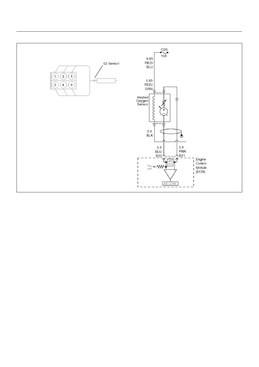
Diagnostic Trouble Code (DTC) P0132 (Flash DTC) HO2S Circuit High Voltage
060RW054
Circuit Description
The Engine Control Module ECM supplies a bias voltage
of about 450 mV between the heated oxygen sensor
(HO2S) signal high and signal low circuits. When
measured with a 10 megaohm digital voltmeter, this may
display as low as 320 mV. The oxygen sensor varies the
voltage within a range of about 1000 mV when the
exhaust is rich, down through about 10 mV when exhaust
is lean. The ECM constantly monitors the HO2S signal
during “closed loop” operation and compensates for a rich
or lean condition by decreasing or increasing injector
pulse width as necessary. If the HO2S voltage remains
excessively high for an extended period of time, DTC
P0132 will be set.
Conditions for Setting the DTC
D
No related DTCs.
D
Engine coolant temperature is between 70
°
C and
110
°
C.
D
“Closed loop” commanded air/fuel ratio is between
14.5 and 14.8.
D
Throttle angle is between 3% and 19%.
D
Vehicle speed is between 0Km/H and 120Km/H.
D
The O
2
sensor voltage reading is below 600m volts for
50 second.
Action Taken When the DTC Sets
D
The ECM will illuminate the malfunction indicator lamp
(MIL) the first time the fault is detected.
D
The ECM will store conditions which were present
when the DTC was set as Freeze Frame and in the
Failure Records data.
D
“Open loop” fuel control will be in effect.
Conditions for Clearing the MIL/DTC
D
The ECM will turn the MIL “OFF” on the third
consecutive trip cycle during which the diagnostic has
been run and the fault condition is no longer present.
D
A history DTC P0132 will clear after 40 consecutive
warm-up cycles have occurred without a fault.
D
DTC P0132 can be cleared by using the Tech 2 “Clear
Info” function or by disconnecting the ECM battery
feed.
Diagnostic Aids
Check the following items:
D
Fuel pressure – The system will go rich if pressure is
too high. The ECM can compensate for some
increase. However, if fuel pressure is too high, a DTC
P0132 may be set. Refer to
Fuel System Diagnosis.
D
Perform “Injector Balance Test” – Refer to
Fuel System
Diagnosis.
D
Check the canister for fuel saturation – If full of fuel,
check canister control and hoses.
D
MAF sensor –The system can go rich if MAF sensor
signal indicates an engine airflow measurement that is
not correct. Disconnect the MAF sensor to see it the
rich condition is corrected. If so, replace the MAF
sensor.
Нет комментариевНе стесняйтесь поделиться с нами вашим ценным мнением.
Текст