Isuzu D-Max / Isuzu Rodeo (TFR/TFS). Manual — part 233
ENGINE DRIVEABILITY AND EMISSIONS
6E–173
Diagnostic Aids
An intermittent may be caused by a poor connection,
rubbed-through wire insulation or a wire broken inside
the insulation. Check for:
• Poor connection - Inspect the ECM harness and
connectors for improper mating, broken locks,
improperly formed or damaged terminals, and poor
terminal-to-wire connection.
• Damaged harness - Inspect the wiring harness for
damage; shorts to ground, shorts to battery positive
and open circuits. If the harness appears to be OK,
disconnect the ECM, turn the ignition on and observe
a voltmeter connected to the 58X reference circuit at
the ECM harness connector while moving connectors
and wiring harnesses related to the ECM. A change
in voltage will indicate the location of the fault.
Diagnostic Trouble Code (DTC) P0336
Crankshaft Position Sensor Circuit Range/performance (58x)
Diagnostic Trouble Code (DTC) P0337
Crankshaft Position Sensor Circuit Low Input (58x)
Step
Action
Value(s)
Yes
No
1
Was the “On-Board Diagnostic (OBD) System Check”
performed?
—
Go to Step 2
Go to On Board
Diagnostic
(OBD) System
Check
2
1. Connect the Tech 2.
2. Review and record the failure information.
3. Select “F0: Read DTC Infor By Priority” in “F0:
Diagnostic Trouble Code”.
Is the DTC P0336 or P0337 stored as “Present
Failure”?
—
Go to Step 3
Refer to
Diagnostic Aids
and Go to Step
3
3
1. Using the Tech2, ignition “On” and engine “Off”.
2. Select “Clear DTC Information” with the Tech2 and
clear the DTC information.
3. Operate the vehicle and monitor the “F5: Failed
This Ignition” in “F2: DTC Information”.
Was the DTC P0336 or P0337 stored in this ignition
cycle?
—
Go to Step 4
Refer to
Diagnostic Aids
and Go to Step
4
4
Check for poor/faulty connection at the CKP sensor or
ECM connector. If a poor/faulty connection is found,
repair the faulty terminal.
Was the problem found?
—
Verify repair
Go to Step 5
5
Visually check the CKP sensor. If a faulty installation is
found, repair as necessary.
Was the problem found?
—
Verify repair
Go to Step 6
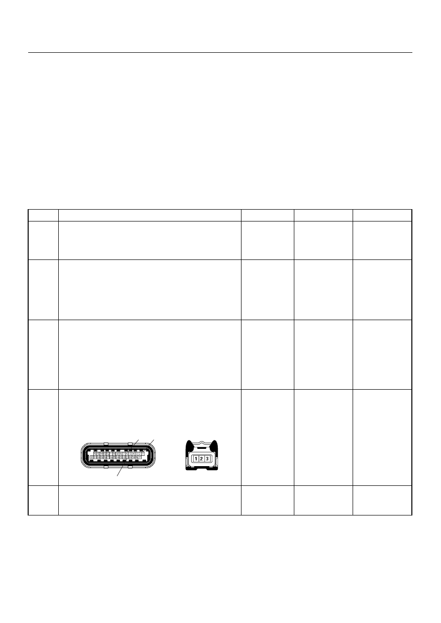
21
6
1
E-60(J1)
E-59
6E–174
ENGINE DRIVEABILITY AND EMISSIONS
6
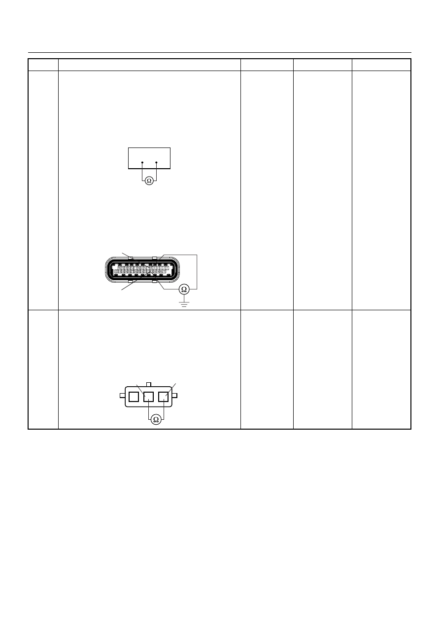
Using the DVM and check the CKP sensor circuit.
Breaker box is available:
1. Ignition “Off”, engine “Off”.
2. Install the breaker box as type A. (ECM
disconnected) Ref. 6E-80.
3. Check the resistance of the CKP sensor.
Was the DVM indicated specified value?
Breaker box is not available:
1. Ignition “Off”, engine “Off”.
2. Disconnect the ECM connector.
3. 3. Check the resistance of the CKP sensor.
Was the DVM indicated specified value?
Approximately
0.55k
Ω at
20°C
Go to Step 10
Go to Step 7
7
Using the DVM and check the CKP sensor circuit.
1. Ignition “Off”, engine “Off”.
2. Disconnect the CKP sensor connector.
3. Check the resistance of the CKP sensor.
Was the DVM indicated specified value?
Approximately
0.55k
Ω at
20°C
Go to Step 8
Go to Step 14
Step
Action
Value(s)
Yes
No
6
21
6
21
E-60(J1)
1
2
3
CKP Sensor
1
2
ENGINE DRIVEABILITY AND EMISSIONS
6E–175
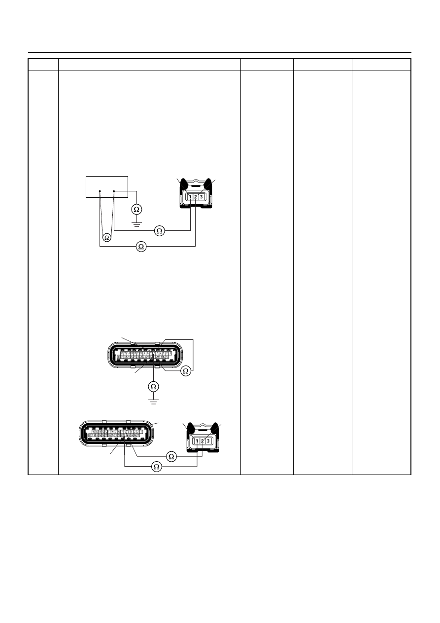
8
Using the DVM and check the CKP sensor circuit.
Breaker box is available:
1. Ignition “Off”, engine “Off”.
2. Install the breaker box as type A. (ECM
disconnected) Ref. 6E-80.
3. Disconnect the CKP sensor connector.
4. Check the circuit for open, short to sensor wire or
short to ground circuit.
Was the problem found?
Breaker box is not available:
1. Ignition “Off”, engine “Off”.
2. Disconnect the ECM connector.
3. Disconnect the CKP sensor connector.
4. Check the circuit for open, short to sensor wire or
short to ground circuit.
Was the problem found?
—
Repair faulty
harness and
verify repair
Go to Step 9
Step
Action
Value(s)
Yes
No
6
21
E-59
2
1
6
E-60(J1)
21
E-59
E-60(J1)
6
21
2
1
6E–176
ENGINE DRIVEABILITY AND EMISSIONS
9
Using the DVM and check the CKP sensor circuit.
1. Ignition “On”, engine “Off”.
2. Disconnect the CKP sensor connector.
3. Check the circuit for short to power supply circuit.
If the DVM indicated out of specified value, repair
faulty harness and verify repair.
Is the action complete?
Less than 1V
Verify repair
—
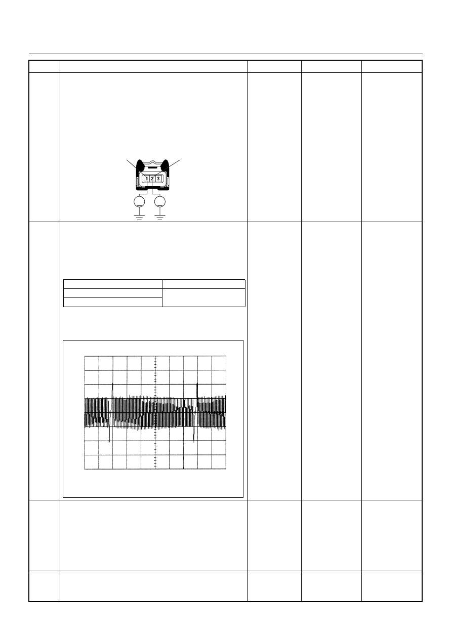
10
Using the DVM and check the CKP sensor signal.
1. Ignition “On”, engine “On”.
2. Measure the CKP output voltage at the sensor
and ECM.
Does the tester indicate standard voltage?
If a oscilloscope is available, monitor the CKP sensor
signal. Does the oscilloscope indicate correct wave
form?
Go to Step 13
Go to Step 11
11
Remove the CKP sensor from the flywheel housing
and visually check.
Check for the following conditions.
• Objects sticking the CKP sensor.
• Objects sticking the CKP sensor pulser.
If a problem is found, repair as necessary.
Was the problem found?
—
Verify repair
Go to Step 12
12
Check the CKP sensor shield wire for open or short
circuit.
Was the problem found?
—
Repair faulty
harness and
verify repair
Go to Step 13
Step
Action
Value(s)
Yes
No
V
V
E-59
2
1
Measurement Point
Voltage (V) (AC Range)
At CKP sensor terminal 1 & 2
Approx. 3.7V in engine idle
Approx. 7.7V at 2000rpm
At ECM E60 (J1) connector 21 & 6
CKP Sensor Signal Reference Wave Form
0V
→
Measurement Terminal: J1-21 (+) J1-6 (-)
Measurement Scale: 10V/div
5.0ms/div
Measurement Condition: Engine speed at 2000rpm
Нет комментариевНе стесняйтесь поделиться с нами вашим ценным мнением.
Текст