Isuzu D-Max / Isuzu Rodeo (TFR/TFS). Manual — part 1042
CLUTCH 7C-27
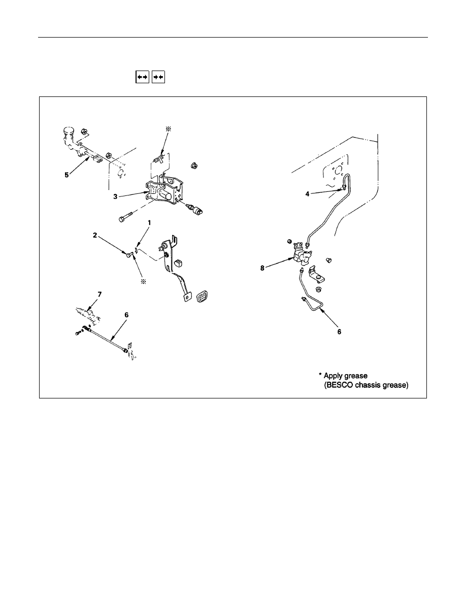
CLUTCH CONTROL
REMOVAL AND INSTALLATION
Except 6VD1 Engine
Removal Steps
1. Pin
2. Jaw joint pin
3. Pedal assembly
4. Oil line
5. Master cylinder assembly
6. Oil line
7. Slave cylinder assembly
8. Damper cylinder assembly
Installation Steps
To install, follow the removal steps in the
reverse order.
7C-28 CLUTCH
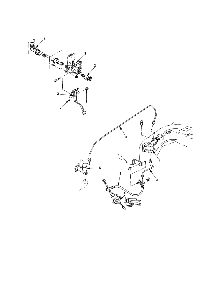
6VD1 RHD Model
Removal Steps
1. Pin and jaw joint pin
2. Pedal assembly and switch
3. Oil line pipe
4. Slave cylinder assembly and heat
protector
5. Master cylinder assembly
6. Damper cylinder assembly
Installation Steps
To install, follow the removal steps in the
reverse order.
CLUTCH 7C-29
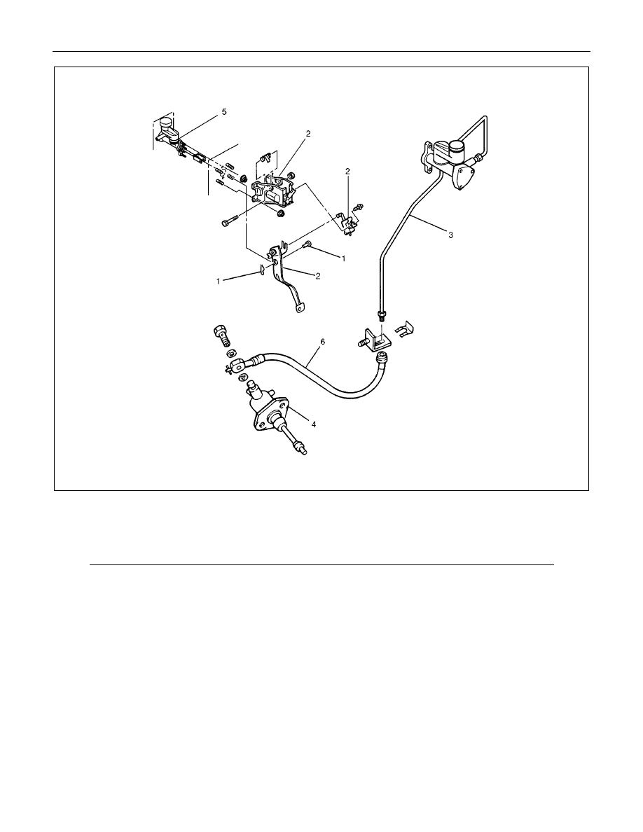
6VD1 LHD Model
Removal Steps
1. Pin and jaw joint pin
2. Pedal assembly and switch
3. Oil line pipe
4. Slave cylinder assembly
5. Master cylinder assmebly
6. Oil line hose
Installation Steps
To install, follow the removal steps in the
reverse order.

7C-30 CLUTCH
MASTER CYLINDER (Except 6VD1 Engine)
DISASSEMBLY
★
Repair Kit
Disassembly Steps
1. Oil tank band
2. Oil tank assembly
3. Joint
4. Lock nut
5. Dust cover
6. Stopper ring
7. Stopper
8. Push rod
9. Piston assembly
10. Cylinder body
Important : Take care not to disassemble the push rod stopper for master cylinder which calk to the master cylinder
body due to the component parts do not disassemble.
Нет комментариевНе стесняйтесь поделиться с нами вашим ценным мнением.
Текст