Isuzu D-Max / Isuzu Rodeo (TFR/TFS). Manual — part 1043
CLUTCH 7C-31
INSPECTION AND REPAIR
Make the necessary adjustments, repairs, and part replacements if excessive wear or damage is discovered during
inspection.
Cylinder Body
1. Clean the cylinder body.
2. Check the fluid return port for restrictions and clean it if
necessary.
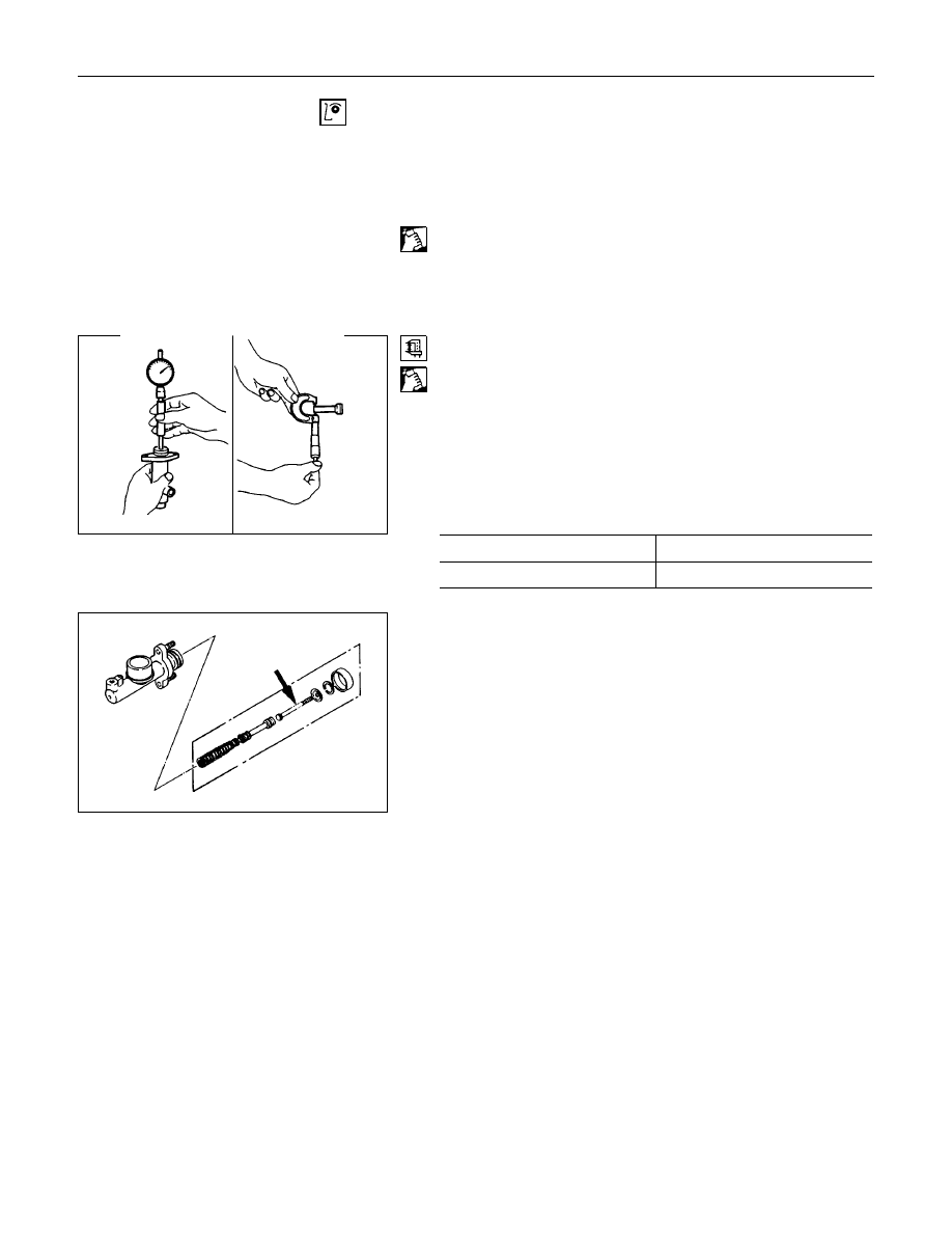
Cylinder Bore and piston Clearance
1. Clean the cylinder body and the piston.
2. Use an inside dial indicator to measure the cylinder bore.
3. Use a micrometer to measure the piston diameter.
4. Calculate the clearance between the cylinder bore and the
piston diameter.
If the clearance exceeds the limit, the entire slave cylinder
assembly must be replaced.
Cylinder Bore and Piston Clearance
mm(in)
Standard
Limit
0.07 (0.0028)
0.15 (0.006)
Inner Parts
Replace the inner parts with new parts shown in the illustration.
7C-32 CLUTCH
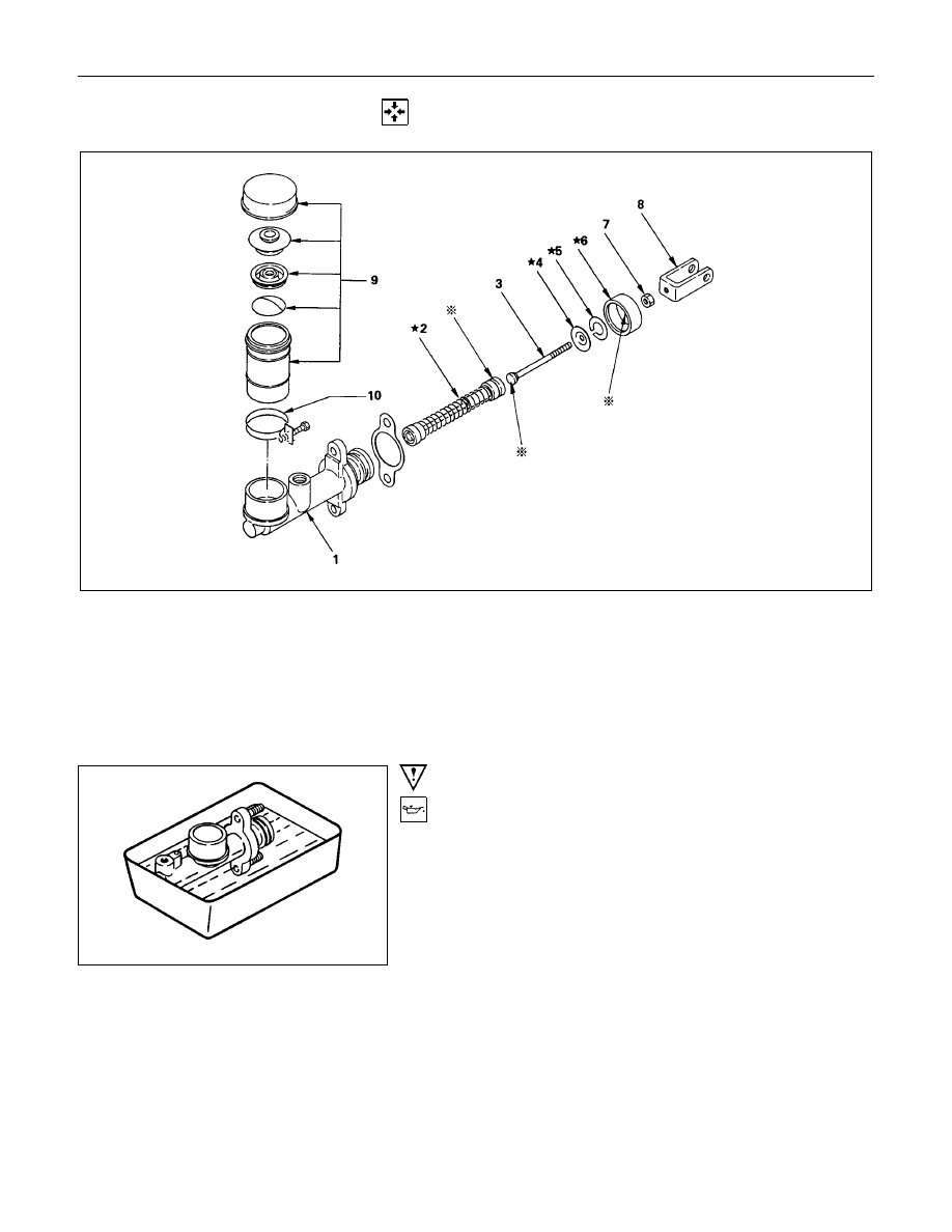
REASSEMBLY
* Apply grease
(COSMO rubber grease)
★
Repair Kit
Reassembly Steps
▲
1. Cylinder body
2. Piston and assembly
3. Push rod
4. Stopper
5. Stopper ring
6. Dust cover
7. Lock nut
8. Joint
9. Oil tank assembly
10. Oil tank band
Important Operations
1. Cylinder Body
Immerse the cylinder body in clean brake fluid.
CLUTCH 7C-33
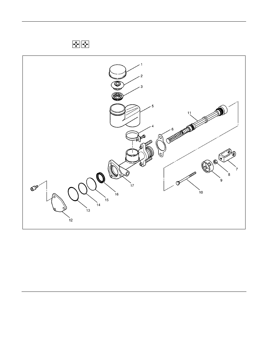
Master Cylinder (6VD1 LHD Model)
DISASSEMBLY AND REASSEMBLY
Disassembly Steps
1. Reservoir cap
2. Base cap
3. Seal
4. Clip
5. Reservoir
6. Gasket
7. Yoke
8. Nut
9. Rod stopper
10. Push rod
11. Piston assembly
12. Plate
13. O-ring
14. Damper ring
15. Diaphragm
16. Seal ring
17. Cylinder body
Reassembly Steps
To reassemble, follow disassembly
steps in the reverse order.
Disassembly
1. Disassemble reservoir cap 1., base cap 2., seal
3., clip 4., and reservoir 5..
2. Disassembly gasket 6., yoke 7., and nut 8..
3. Disassemble rod stopper 9., push rod 10., and
piston assembly 11..
4. Disassemble plate 12., o-ring 13., damper ring
14., diaphragm 15., and seal ring 16. from
cylinder body 17..
7C-34 CLUTCH
Inspection and Repair
Make the necessary adjustments, repair, and part
replacements if excessive wear or damage is
discovered during inspection.
Cylinder Body
1. Clean the cylinder body.
2. Check the fluid return port for restrictions and clean
it if necessary.
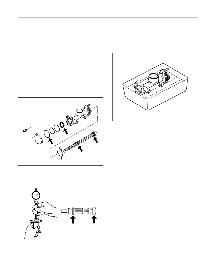
Inner Parts
1. Visually inspect the disassembled parts for
excessive wear and damage.
Replace the inner parts with new parts shown in the
illustration.
2. Measure the clearance between master cylinder
wall and piston.
If the measured value exceeds the specified limit,
the master cylinder assembly must be replaced.
Standard: 0.07 mm (0.0028 in)
Limit: 0.15 mm (0.0059 in)
Reassembly
To reassemble, follow the disassembly steps in the
reverse order, noting the following points:
Cylinder Body
Immerse the cylinder body in clean brake fluid.
Piston Assembly
Before installing, apply a thin coat of rubber grease to
the piston. Install cup in groove in piston with lip turned
to front of cylinder. Use care to prevent damaging the
lip of the piston seat.
Нет комментариевНе стесняйтесь поделиться с нами вашим ценным мнением.
Текст