Isuzu D-Max / Isuzu Rodeo (TFR/TFS). Manual — part 178
6E–316
4JH1 ENGINE DRIVEABILITY AND EMISSIONS
31
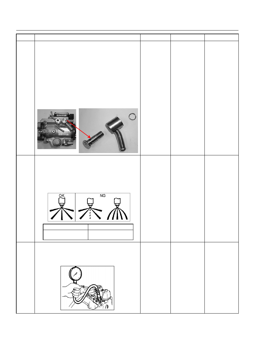
Remove the eye bolt with gauze filter from the
injection pump and check for the following conditions.
• Objects blocking at the gauze filter. Check for a
condition that causes contaminated fuel, such as
the customer is using an aftermarket fuel filter or
extended maintenance interval.
• Check for a condition that causes fuel waxing or
icing, such as the customer is using an incorrect
fuel type in winter season or water mixed with the
fuel.
If a problem is found, repair as necessary.
Was the problem found?
—
Replace the eye
bolt with gauze
filter and verify
repair
Go to Step 32
32
Remove the injection nozzles from the engine and
check for the following conditions.
• Improper splay condition.
• Operating pressure is incorrect.
If a problem is found, repair as necessary.
Was the problem found?
—
Replace the
injection nozzle
and verify repair
Go to Step 33
33
Check the engine compression pressure for each
cylinders.
If a problem is found, repair as necessary.
Was the problem found?
More than 30
Mpa (31.0 kg/
cm
2
)
Verify repair
Go to Step 34
Step
Action
Value(s)
Yes
No
1
st
Stage
2
nd
Stage
20.0 - 21.0 Mpa
(204 - 214 kg/cm
2
)
34.3 - 35.8 Mpa
(350 - 365 kg/cm
2
)

4JH1 ENGINE DRIVEABILITY AND EMISSIONS
6E–317
34
Check the inlet/exhaust valve clearance for each
valves.
Are the valve clearances within the specified value?
0.4mm at cold
(In/Ex)
Go to Step 35
Adjust and
verify repair
35
1. Review all diagnostic procedures within this table.
2. If all procedures have been completed and no
malfunctions have been found, review/inspect the
following:
• Visual/physical inspection
• Tech 2 data
• All electrical connections within a suspected circuit
and/or system
Was a problem found?
—
Verify repair
Go to Step 36
36
Is the ECM programmed with the latest software
release?
If not, download the latest software to the ECM using
the “SPS (Service Programming System)”.
Was the problem solved?
—
Verify repair
Go to Step 37
37
Substitute a known good ECM and recheck.
Was the problem solved?
IMPORTANT: The replacement ECM must be
programmed. Refer to section of the Service
Programming System (SPS) in this manual.
Following ECM programming, the immobiliser system
(if equipped) must be linked to the ECM. Refer to
section 11 “Immobiliser System-ECM replacement” for
the ECM/Immobiliser linking procedure.
—
Go to Step 38
Go to Step 39
38
Replace the ECM.
Is the action complete?
IMPORTANT: The replacement ECM must be
programmed. Refer to section of the Service
Programming System (SPS) in this manual.
Following ECM programming, the immobiliser system
(if equipped) must be linked to the ECM. Refer to
section 11 “Immobiliser System-ECM replacement” for
the ECM/Immobiliser linking procedure.
—
Verify repair
—
39
Replace the injection pump assembly.
Is the action complete?
—
Verify repair
—
Step
Action
Value(s)
Yes
No

6E–318
4JH1 ENGINE DRIVEABILITY AND EMISSIONS
SURGES AND/OR CHUGS SYMPTOM
DEFINITIONS: Engine power variation under steady
throttle or cruise. Feels like the vehicle speeds up and
slows down with no charge in the accelerator pedal.
time
rpm
Surge
Step
Action
Value(s)
Yes
No
1
Was the “On-Board Diagnostic (OBD) System Check”
performed?
—
Go to Step 2
Go to On Board
Diagnostic
(OBD) System
Check
2
1. Perform a bulletin search.
2. If a bulletin that addresses the symptom is found,
correct the condition as instructed in the bulletin.
Was a bulletin found that addresses the symptom?
—
Verify repair
Go to Step 3
3
Was a visually/physical check performed?
—
Go to Step 4
Go to Visual /
physical Check
4
Is the customer using the incorrect fuel type?
Diesel fuel
only
Replace with
diesel fuel
Go to Step 5
5
Visually/physically inspect for the following conditions.
• Restrict air intake system. Check for a restricted air
filter element, or foreign objects blocking the air
intake system
• Check for objects blocking or excessive deposits in
the throttle bore and on the throttle plate
• Check for a condition that causes a large vacuum
leak, such as an incorrectly installed or faulty
crankcase ventilation hose.
• Restrict air intake system at the turbocharger.
Check for objects blocking the turbocharger
compressor wheel or turbine shaft sticking.
If a problem is found, repair as necessary.
Was a problem found?
—
Verify repair
Go to Step 6
6
Check the ECM & PSG grounds to verify that they are
clean and tight. Refer to the ECM wiring diagrams.
Was a problem found?
—
Verify repair
Go to Step 7
7
1. Using the Tech 2, ignition “On” and engine “Run”.
2. Monitor the “A/C Information Switch” in the data
display.
Does the Tech 2 indicate correct “A/C Information
Switch” status depending on A/C switch position?
If a problem is found, repair as necessary.
Was the problem found?
—
Verify repair
Go to Step 8

4JH1 ENGINE DRIVEABILITY AND EMISSIONS
6E–319
8
1. Using the Tech 2, display the ECT sensor and IAT
sensor value.
2. Check the displayed value.
Does the Tech 2 indicate correct temperature
depending on engine condition?
If a problem is found, repair as necessary.
Was the problem found?
—
Verify repair
Go to Step 9
9
1. Using the Tech 2, ignition “On” and engine “Run”.
2. Monitor the “Mass Air Flow” in the data display.
Does the Tech 2 indicate correct “Mass Air Flow”
depending on accelerator pedal operation?
—
Go to Step 14
Go to Step 10
10
Remove the MAF & IAT sensor assembly and check
for the following conditions.
• Objects blocking at the MAF sensor element.
If a problem is found, repair as necessary.
Was the problem found?
—
Verify repair
Go to Step 11
11
Check the MAF sensor harness for the following
conditions.
• Check for poor connector connection.
• Check for misrouted harness.
• Check for any accessory parts which may cause
electric interference.
If a problem is found, repair as necessary.
Was a problem found?
—
Verify repair
Go to Step 12
12
Substitute a known good MAF & IAT sensor assembly
and recheck.
Was the problem solved?
—
Go to Step 13
Go to Step 29
13
Replace the MAF & IAT sensor assembly.
Is the action complete?
—
Verify repair
—
14
1. Using the Tech 2, ignition “On” and engine “Off”.
2. Monitor the “Pedal/Throttle Position” and “Idle
Switch” in the data display.
Does the Tech 2 indicate correct “Pedal/Throttle
Position” from 0% to 100% and correct “Idle Switch”
status depending on accelerator pedal operation?
—
Go to Step 19
Go to Step 15
15
1. Using the Tech 2, ignition “On” and engine “Off”.
2. Monitor the “Pedal/Throttle Position” and “Idle
Switch” in the data display.
3. Adjust the accelerator cable or TPS within 0% to
100%.
Was the problem solved?
—
Verify repair
Go to Step 16
16
Check the TPS harness for the following conditions.
• Check for poor connector connection.
• Check for misrouted harness.
• Check for any accessory parts which may cause
electric interference.
If a problem is found, repair as necessary.
Was a problem found?
—
Verify repair
Go to Step 17
17
Substitute a known good TPS and recheck.
Was the problem solved?
—
Go to Step 18
Go to Step 29
18
Replace the TPS.
Is the action complete?
—
Verify repair
—
Step
Action
Value(s)
Yes
No
Нет комментариевНе стесняйтесь поделиться с нами вашим ценным мнением.
Текст