Isuzu D-Max / Isuzu Rodeo (TFR/TFS). Manual — part 177

6E–312
4JH1 ENGINE DRIVEABILITY AND EMISSIONS
8
1. Using the Tech 2, ignition “On” and engine “Off”.
2. Monitor the “Neutral Switch” in the data display.
Does the Tech 2 indicate correct “Neutral Switch”
status depending on any shift positions?
If a problem is found, repair as necessary.
Was the problem found?
—
Verify repair
Go to Step 9
9
1. Using the Tech 2, ignition “On” and engine “Run”.
2. Monitor the “A/C Information Switch” in the data
display.
Does the Tech 2 indicate correct “A/C Information
Switch” status depending on A/C switch position?
If a problem is found, repair as necessary.
Was the problem found?
—
Verify repair
Go to Step 10
10
1. Using the Tech 2, display the ECT sensor and IAT
sensor value.
2. Check the displayed value.
Does the Tech 2 indicate correct temperature
depending on engine condition?
If a problem is found, repair as necessary.
Was the problem found?
—
Verify repair
Go to Step 11
11
1. Using the Tech 2, ignition “On” and engine “Run”.
2. Monitor the “Mass Air Flow” in the data display.
Does the Tech 2 indicate correct “Mass Air Flow”
depending on accelerator pedal operation?
—
Go to Step 16
Go to Step 12
12
Remove the MAF & IAT sensor assembly and check
for the following conditions.
• Objects blocking at the MAF sensor element.
If a problem is found, repair as necessary.
Was the problem found?
—
Verify repair
Go to Step 13
13
Check the MAF sensor harness for the following
conditions.
• Check for poor connector connection.
• Check for misrouted harness.
• Check for any accessory parts which may cause
electric interference.
If a problem is found, repair as necessary.
Was a problem found?
—
Verify repair
Go to Step 14
14
Substitute a known good MAF & IAT sensor assembly
and recheck.
Was the problem solved?
—
Go to Step 15
Go to Step 36
15
Replace the MAF & IAT sensor assembly.
Is the action complete?
—
Verify repair
—
16
1. Using the Tech 2, ignition “On” and engine “Off”.
2. Monitor the “Pedal/Throttle Position” and “Idle
Switch” in the data display.
Does the Tech 2 indicate correct “Pedal/Throttle
Position” from 0% to 100% and correct “Idle Switch”
status depending on accelerator pedal operation?
—
Go to Step 21
Go to Step 17
Step
Action
Value(s)
Yes
No

4JH1 ENGINE DRIVEABILITY AND EMISSIONS
6E–313
17
1. Using the Tech 2, ignition “On” and engine “Off”.
2. Monitor the “Pedal/Throttle Position” and “Idle
Switch” in the data display.
3. Adjust the accelerator cable or TPS within 0% to
100%.
Was the problem solved?
—
Verify repair
Go to Step 18
18
Check the TPS harness for the following conditions.
• Check for poor connector connection.
• Check for misrouted harness.
• Check for any accessory parts which may cause
electric interference.
If a problem is found, repair as necessary.
Was a problem found?
—
Verify repair
Go to Step 19
19
Substitute a known good TPS and recheck.
Was the problem solved?
—
Go to Step 20
Go to Step 36
20
Replace the TPS.
Is the action complete?
—
Verify repair
—
21
Remove the CKP sensor from the flywheel housing
and check for the following conditions.
• Objects sticking the CKP sensor.
• Objects sticking the CKP sensor pulser.
If a problem is found, repair as necessary.
Was the problem found?
—
Verify repair
Go to Step 22
22
Check the CKP sensor harness for the following
conditions.
• Check for poor connector connection.
• Check for misrouted harness.
• Check for any accessory parts which may cause
electric interference.
If a problem is found, repair as necessary.
Was a problem found?
—
Verify repair
Go to Step 23
23
Substitute a known good CKP sensor and recheck.
Was the problem solved?
—
Go to Step 24
Go to Step 25
24
Replace the CKP sensor.
Is the action complete?
—
Verify repair
—
Step
Action
Value(s)
Yes
No
6E–314
4JH1 ENGINE DRIVEABILITY AND EMISSIONS
25
1. Using the Tech 2 and ignition “On” and engine
“Run”.
2. Monitor the following parameters in the data
display.
• “Desired Injection Quantity” & “Injection Quantity”
• “Desired Injection Start” & “Actual Injection Start”
Are the large gap or unstable parameter displayed
between “Desired” and “Actual”?
—
Go to Step 29
Go to Step 26
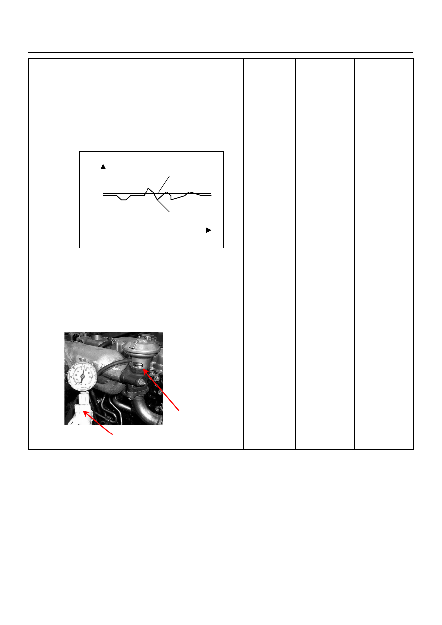
26
Using the vacuum pump and check the EGR valve (if
equipped) operation for the following condition through
the small window.
• Restrict shaft movement. Check for objects sticking
the shaft, broken diaphragm or excessive carbon
deposit.
If a problem is found, repair as necessary.
Was a problem found?
—
Verify repair
Go to Step 27
Step
Action
Value(s)
Yes
No
When idling or part-throttle
High
Desired
Low
Time
Actual
Vacuum Pump
Small Window
4JH1 ENGINE DRIVEABILITY AND EMISSIONS
6E–315
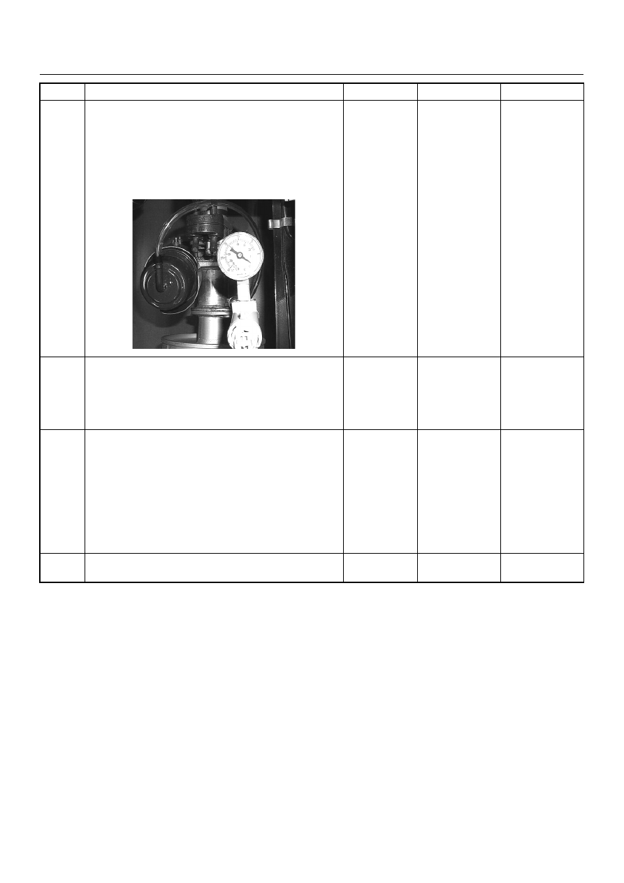
27
Using the vacuum pump and check the exhaust
throttle valve (if equipped) operation for the following
condition.
• Restrict shaft movement. Check for objects sticking
the shaft, broken diaphragm or excessive carbon
deposit.
Was a problem found?
—
Verify repair
Go to Step 28
28
Check the exhaust system for a possible restriction.
• Damaged or collapsed pipes or catalytic converter.
• Internal muffler failure.
If a problem is found, repair as necessary.
Was a problem found?
—
Verify repair
Go to Step 29
29
Visually/physically inspect for the following conditions.
• Restrict fuel supply system. Check for a pinched
fuel hose/pipe.
• Check for a condition that causes fuel waxing or
icing, such as the customer is using an incorrect
fuel type in winter season or water mixed with the
fuel.
If a problem is found, repair as necessary.
Was a problem found?
—
Verify repair
Go to Step 30
30
Replace the fuel filter.
Was the problem solved?
—
Verify repair
Go to Step 31
Step
Action
Value(s)
Yes
No
Нет комментариевНе стесняйтесь поделиться с нами вашим ценным мнением.
Текст