Isuzu D-Max / Isuzu Rodeo (TFR/TFS). Manual — part 1714

6D3-14 STARTING AND CHARGING SYSTEM
7. To remove the pulley, mount an 8mm Allen key in the vice
with the short end upwards, place a 24mm ring spanner on
the puley nut, position the internal hexagon of the rotor shaft
onto the Allen ken, loosen the nut and remove the pulley.
Note: the pulley has an integral boss which locks up against
the bearing,
therefore no thrust collar is provided.
8. Removing the rotor assembly. Remove the four retaining
screws from the drive end housing, withdraw the rotor
complete with the bearing.
Note: the rotor must not be pressed from the drive end housing
using a press as the bearing retaining plate and drive end
housing will be damaged or distorted. Parts removed in this
way must be replaced if the integrity of the generator is to be
maintained.
9. Remove the drive end bearing from the rotor shaft using a
chuck type puler, take care not to distort the fan assembly
during this process.
10.Remove the slipring end bearing using the same meghod
as in 9.
Clean
Thoroughly clean all components except the rotor and stator
with an approved cleaning agent. Ensure that all traced of oil
and dirt are removed. If an abrasive cleaner is used to remove
scale and paint from the housings take care not to abrade the
bearing and mounting spigot surfaces. The rotor and stator
must be cleaned with compressed air only, the use of solvents
could cause damage to the insulating materials.
Inspection
1. Rectifier assembly
The following test equipment is required.
The recitifier assembly is not repairable and must be replaced
if a faulty diode is detected during inspection.
(a) Adiode tester where the DC output at the test probes does
not exceed 14 volts or in the case of AC testers 12 volts
RMS. This is to ensue that when inspection rectifiers fitted
with zener power diodes the forward and reverse checks
are completer and are not masked by the diode turning on
due to the zener breakdown voltage.
(b) A zenere diode tester with a DC output in excess of 30
volts, the tester should also incorporate internal current
limiting set to 5 Ma. to prevent high currents during
inspection.
(c) Diodes can be destroyed during service due to high
temperature and overload, open circuits are usually a result
of excessive voltage.
STARTING AND CHARGING SYSTEM 6D3-15
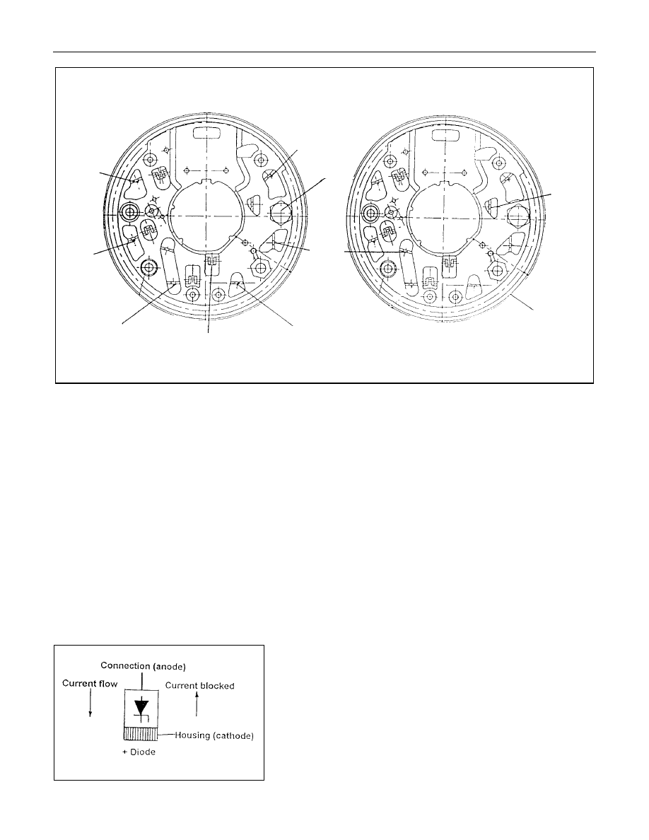
Positive heatsink
8 diode
6 diode
H
G
Negative heatsink
C
B
A
Starpoint
F
E
B+Bolt
D
Diode connections
Stator connection
1.1
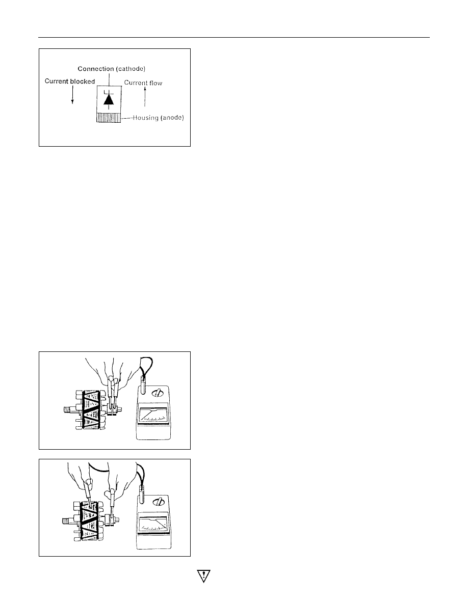
Power Diodes.
Apply the negative test probe of the diode tester or a
multimeter with a diode test feature to the positive heatsink and
the positive probe alternatevely to A,B,C, a low resistance
reading, or the forward voltage drop across the diode shoud be
obtained. Reverse the test probes, a high resistance reading or
a higher reverse voltage should be obtained.
Now connect the positive test probe to the negative heatsink
and the negative alternatively to D,E,F, a low resistance or
forward voltage drop across the diode should be obtained.
Reverse the test probes, a high resistance reading or a higher
reverse voltage should be obtained.
For 8 diode rectifier plates tests for G and H should be
included. When the reverse voltage test is done the applied
voltage should be less than 14 volts DC or 12 volts RMS for
AC testers.
1.2Zener Diode
The basic tests in 1.1 should be undertaken first before the
diode zener voltage is tested. Diodes are grouped together
according to their zener voltag i.e. all diodes within a rectifier
must have the same zener voltage.
Connect the test probes as for the reverese test listed above
i.e. reverse biased apply the test voltage form the zener diode
tester (current limited to 5ma) and read to zener breakdown
voltage this should be a steady reading and not increase with
increased voltage from the tester.
6D3-16 STARTING AND CHARGING SYSTEM
Readings for Zener diode groups 011 to 042
Zener voltage at
5Ma.
Positive
diode
Negative
diode
Fordward
current Rating
17.8v-19.2v
011
012
25A
18.8v-20.2v
013
014
25A
19.8v-21.2v
015
016
25A
20.8v-22.2v
017
018
25A
21.8v-23.2v
019
020
25A
22.8v-24.2v
021
022
25A
17.8v-19.2v
031
032
35A
18.8v-20.2v
033
034
35A
19.8v-21.2v
035
036
35A
20.8v-22.2v
037
038
35A
21.8v-23.2v
039
040
35A
22.8v-24.2v
041
042
35A
Note: Diode number is stamped on the rear of the diode.
2. Stator
Inspect the stator insulation resistance to ground with an
insuation tester or a series test lamp up to 110 volts.
The insulation resistance must be greater than 1 megohm.
The winding reisistance is measured between phases using a
low reading ohmmeter designed for this purpose, the values
are given at the rear of this instruction.
3. Rotor
Inspect the rotor for insulation resistance to ground using an
insulation tester or a series test lamp up to 110 volts.
The insulation resistance must be grater than 1 megohm.
Measure the rotor resistance between the sliprings using an
ohmmeter or apply 12 volts across the sliprings and measure
the rotor current flow, then divide 12 by the measured current,
the results is the rotor resistance in ohms. values are given at
the rear of this instruction.
If the sliprings are worn or out of round they must be re-
machined to a minimum diameter or 26.7 mm and should have
a runout not exceeding 0.060mm. If the slipring is below these
limits it must be replaced with a new one.
Warning; extreme care must be exercised when machining
the slipring as it is possible for the turning tool to foul the fan.
STARTING AND CHARGING SYSTEM 6D3-17
4. Replacing the brushes (inbuilt regulator)
Check the brushes for length, this is measured from the brush
holder to the end of the brush along it's centre line. Also
inspect for any sideways wear. If worn replace both brushes.
The minimum length is 3.8mm. Inspect the brush springs for
signs of corrosion or loss of tension or uneven tension.
Replacing the brushes, using a soldering iron apply heat to the
soldered joints on the rear of the brush holder of the regulator,
using a small lever prise up the retaining tabs to release the
brush lead and spring. Thread the new brush lead up the
brush holder along with the spring, pull the lead through the
tabs until the brush is protruding 12mm from the holder.
Bend down the tabs and solder the brush lead taking care not
to allow the solder to run up the lead which will reduce
flexibility. Use 60/40 resin cored solder.
5. Ball bearing
Please note the bearings used in this KCA generator are a high
tolerance type, only fully sealed bearings of the same
specification are to be used as replacements. It is
recommended that the bearings be replaced during the
reconditioning process to restore the unit to original
specification.
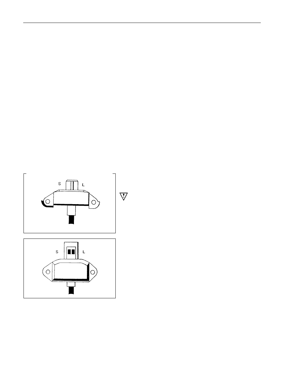
6. Regulator
The regulator can only be tested when fitted into an altenator.
Warning: do not reverse"S" and "L" connections or put 12
volt supply to "L" terminal, this connection must not be
used as a supply source other than to supply the
requirements of the warning lamp 2(watts).
Such action will destroy the regulator warning lamp
circuit.
For test voltages refer to Generator output testing section.
See also additional information on regulator function earlier in
this instruction.
Нет комментариевНе стесняйтесь поделиться с нами вашим ценным мнением.
Текст