Isuzu D-Max / Isuzu Rodeo (TFR/TFS). Manual — part 563
6A – 90 ENGINE MECHANICAL
Piston Grade Selectin
Measure the cylinder liner bore after installing the cylinder
liner. Then select the appropriate piston grade for the
installed cylinder liner.
1. Measure the cylinder liner bore.
Refer to “Cylinder Liner Bore Measurement”
Note:
It is most important that the correct piston grade be
used. Failure to select the correct piston grade will
result in engine failure. Always measure the cylinder
bore and select the correct piston grade.
2. Measure the piston diameter.
Piston Measuring Point
mm (in)
4JA1 70
(2.76)
4JA1T 78
(3.07)
4JB1T 74
(2.91)
4JG2T, 4JH1TC
71 (2.79)
4JA1TC 68.1
(2.68)
Grade
4JA1T/4JA1 4JB1T
4JG2T
AX
92.979 – 92.994
(3.6606 – 3.6612)
92.974 – 92.989
(3.6604 – 3.6610)
95.369 – 95.384
(3.7547 –3.7553)
CX
92.995 – 93.010
(3.6612 – 3.6618)
92.990 – 93.005
(3.6610 – 3.6616)
95.385 – 95.400
(3.7553 – 3.7559)
Grade
4JA1TC 4JH1TC
AX
92.945 – 92.964
(3.6592 – 3.6600)
95.359 – 95.374
(3.7543 – 3.7549)
CX
92.965 – 92.984
(3.6600 – 3.6607)
95.375 – 95.390
(3.7549 – 3.7555)
Cylinder Liner and Piston Clearance
mm (in)
4JA1T/4JA1
0.041 – 0.071 (0.0016 – 0.0027)
4JB1T
0.046 – 0.076 (0.0018 – 0.0030)
4JG2T
0.051 – 0.081 (0.0020 – 0.0032)
4JA1TC
0.057 – 0.095 (0.0022 – 0.0029)
4JH1TC
0.061 – 0.091 (0.0024 – 0.0036)
Note:
Cylinder liner kit clearances are preset. However, the
cylinder liner installation procedure may result in
slight decreases in cylinder liner clearances. Always
measure the cylinder liner clearance after installation
to be sure that it is correct.
ENGINE MECHANICAL 6A – 91
TAPPET AND PUSH ROD
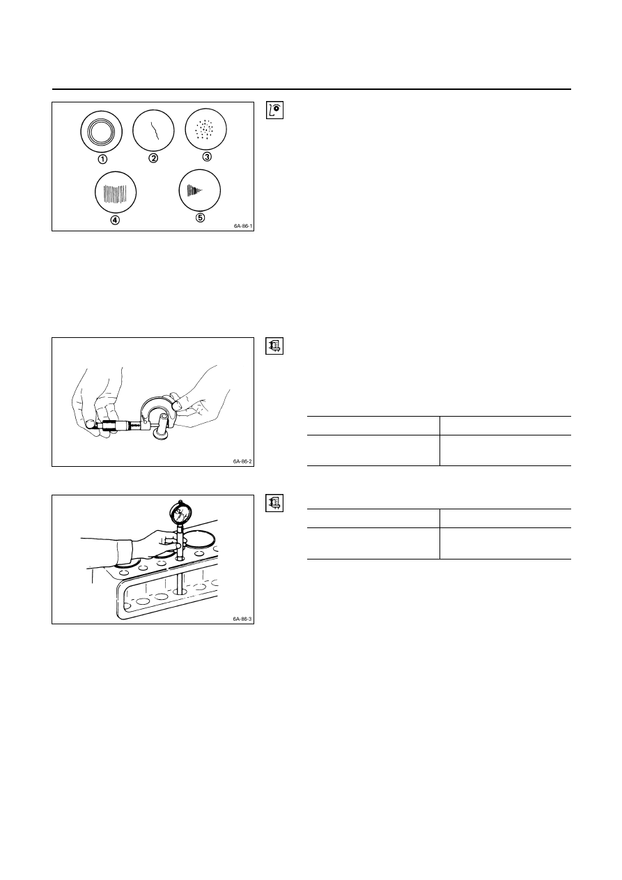
Visually inspect the tappet contact surfaces for pitting,
cracking, and other abnormal conditions. The tappet must
be replaced if any of these conditions are present.
Refer to the illustration at the left.
Q
Normal contact
R
Cracking
S
Pitting
T
Irregular contact Uneven contact
U
Irregular contact One-sided contact
Note:
The tappet surfaces are spherical. Do not attempt to
grind them with an oil stone or similar tool in an effort
to repair the tappet. If the tappet is damaged, it must
be replaced.
Tappet Outside Diameter
Measure the tappet outside diameter with a micrometer.
If the measured value is less than the specified limit, the
tappet must be replaced.
Tappet Outside Diameter
mm (in)
Standard
Limit
12.97 – 12.99
(0.510 – 0.511)
12.95 (0.510)
Tappet and Cylinder Body Clearance
mm (in)
Standard
Limit
0.01 – 0.046
(0.0004 – 0.0018)
0.10 (0.004)
6A – 92 ENGINE MECHANICAL
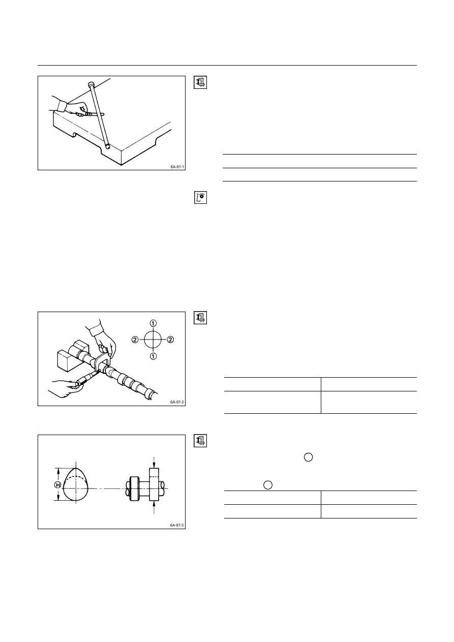
Push Rod Curvature
1. Lay the push rod on a surface plate.
2. Roll the push rod along the surface plate and measure
the push rod curvature with a thickness gauge.
If the measured value exceeds the specified limit, the
push rod must be replaced.
Pushrod Curvature
mm (in)
Limit
0.3 (0.012)
3. Visually inspect both ends of the push rod for
excessive wear and damage. The push rod must be
replaced if these conditions are discovered during
inspection.
CAMSHAFT
Visually inspect the journals, the cams, the oil pump drive
gear, and the camshaft bearings for excessive wear and
damage. The camshaft and the camshaft bearings must
be replaced if these conditions are discovered during
inspection.
Camshaft Journal Diameter
Use a micrometer to measure each camshaft journal
diameter in two directions (
Q
and
R
). If the measured
value is less than the specified limit, the camshaft must be
replaced.
Camshaft Journal Diameter
mm (in)
Standard
Limit
49.945 – 49.975
(1.9663 – 1.9675)
49.60 (1.953)
Cam Height
Measure the cam height
H
with a micrometer. If the
measured value is less than the specified limit, the
camshaft must be replaced.
Cam Height
H
mm
(in)
Standard
Limit
42.08 (1.657)
41.65 (1.640)
ENGINE MECHANICAL 6A – 93
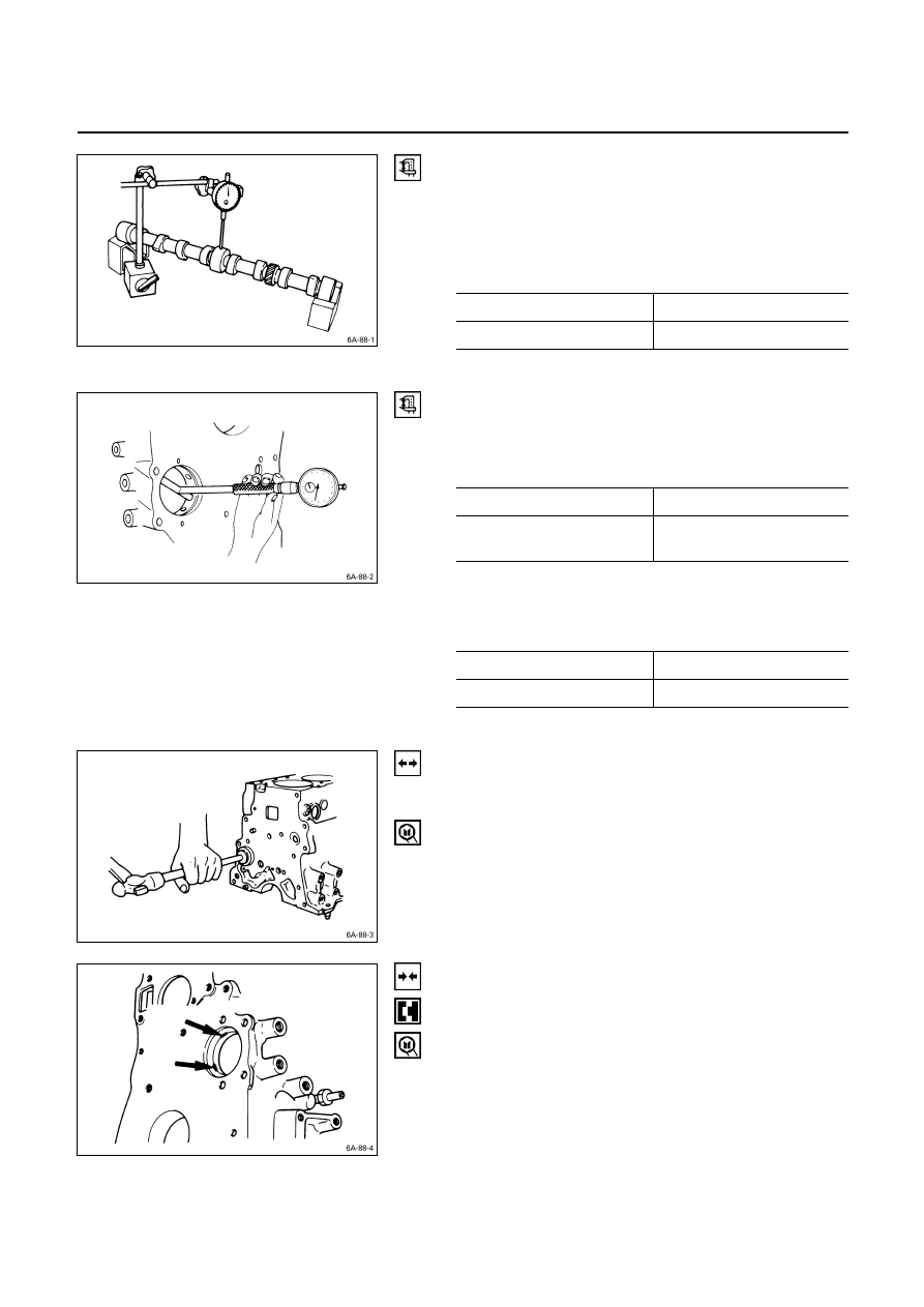
Camshaft Run-Out
1. Mount the camshaft on V-blocks.
2. Measure the run-out with a dial indicator.
If the measured value exceeds the specified limit, the
camshaft must be replaced.
Camshaft Run-Out
mm (in)
Standard Limit
0.02 (0.0008)
0.10 (0.004)
Camshaft and Camshaft Bearing Clearance
Use an inside dial indicator to measure the camshaft
bearing inside diameter.
Crankshaft Bearing Inside Diameter
mm (in)
Standard Limit
50.00 – 50.03
(1.968 – 1.970)
50.08 (1.972)
If the clearance between the camshaft bearing inside
diameter and the journal exceeds the specified limit, the
camshaft bearing must be replaced.
Camshaft Bearing Clearance
mm (in)
Standard Limit
0.05 (0.002)
0.12 (0.005)
Camshaft Bearing Replacement
Camshaft Bearing Removal
1. Remove the cylinder body plug plate.
2. Use the bearing replacer to remove the camshaft
bearing.
Bearing Replacer: 5-8840-2038-0
Camshaft Bearing Installation
1. Align the bearing oil holes with the cylinder body oil
holes.
2. Use the replacer to install the camshaft bearing.
Bearing Replacer: 5-8840-2038-0
Нет комментариевНе стесняйтесь поделиться с нами вашим ценным мнением.
Текст