Isuzu D-Max / Isuzu Rodeo (TFR/TFS). Manual — part 562
6A – 86 ENGINE MECHANICAL
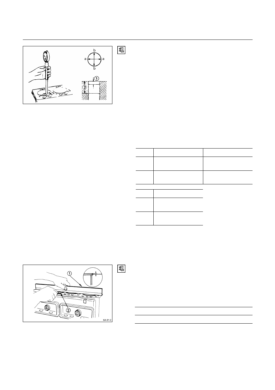
Cylinder Liner Bore Measurement
Use a cylinder indicator to measure the cylinder bore at
measuring point
Q, R
in the thrust a-a and axial b-b
directions of the crankshaft.
If the measured value exceeds the specified limit, the
cylinder liner must be replaced.
Measuring Points
Q
20 mm (0.8 in) for 4JA1, 4JA1TC
and 4JB1T, 4JG2T,
4JH1TC
R
140 mm(5.5 in) for 4JA1, 4JA1TC
R
160 mm(6.3 in) for 4JB1T, 4JG2T,
4JH1TC
Cylinder Liner Bore (Service Part)
mm (in)
Grade
4JA1, 4JA1T, 4JB1T
4JG2T, 4JH1TC
AX
93.035 – 93.050
(3.6628 – 3.6634)
95.435 – 95.450
(3.7573 – 3.7579)
CX
93.051 – 93.066
(3.6634 – 3.6640)
95.451 – 95.466
(3.7579 – 3.7585)
Grade
4JA1TC
AX
93.021 – 93.040
(3.6622 – 3.6630)
CX
93.041 – 93.060
(3.6630 – 3.6638)
012L200001
Note:
The inside of the dry type cylinder liner is chrome
plated. It cannot be rebored or honed.
If the inside of the cylinder liner is scored or
scorched, the cylinder liner must be replaced.
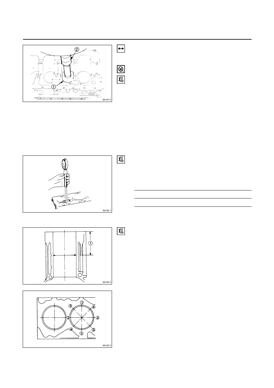
Cylinder Liner Projection Inspection
1. Hold a straight edge
Q
along the top edge of the
cylinder liner to be measured.
2. Use a feeler gauge
R
to measure each cylinder liner
projection.
Cylinder Liner Projection
mm (in)
Standard
0 – 0.1 (0 – 0.004)
The difference in the cylinder liner projection height
between any two adjacent cylinders must not exceed
0.03 mm (0.0012 in).
ENGINE MECHANICAL 6A – 87
Cylinder Liner Replacement
Cylinder Liner Removal
1. Insert the cylinder liner remover
Q
into the cylinder
body (from the lower side of the cylinder body) until it
makes firm contact with the cylinder liner.
Cylinder Liner Remover:
5-8840-2039-0
5-8840-2304-0: 4JG2T, 4JH1TC
Engine
2. Use a bench press
R
to slowly force the cylinder liner
from the cylinder body.
Note:
Take care not to damage the cylinder body upper face
during the cylinder liner removal procedure.
3. Measure the cylinder body upper face warpage.
Refer to “Cylinder Body Upper Face Warpage”.
Cylinder Liner Grade Selection
Subtract the average cylinder body bore from the average
cylinder liner outside diameter to obtain the fitting
interference.
Fitting Interference
mm (in)
Standard
– 0.0010* – 0.019 (– 0.00004* – 0.0007)
* A minus (–) value indicates that the cylinder body bore
is smaller than the liner outside diameter.
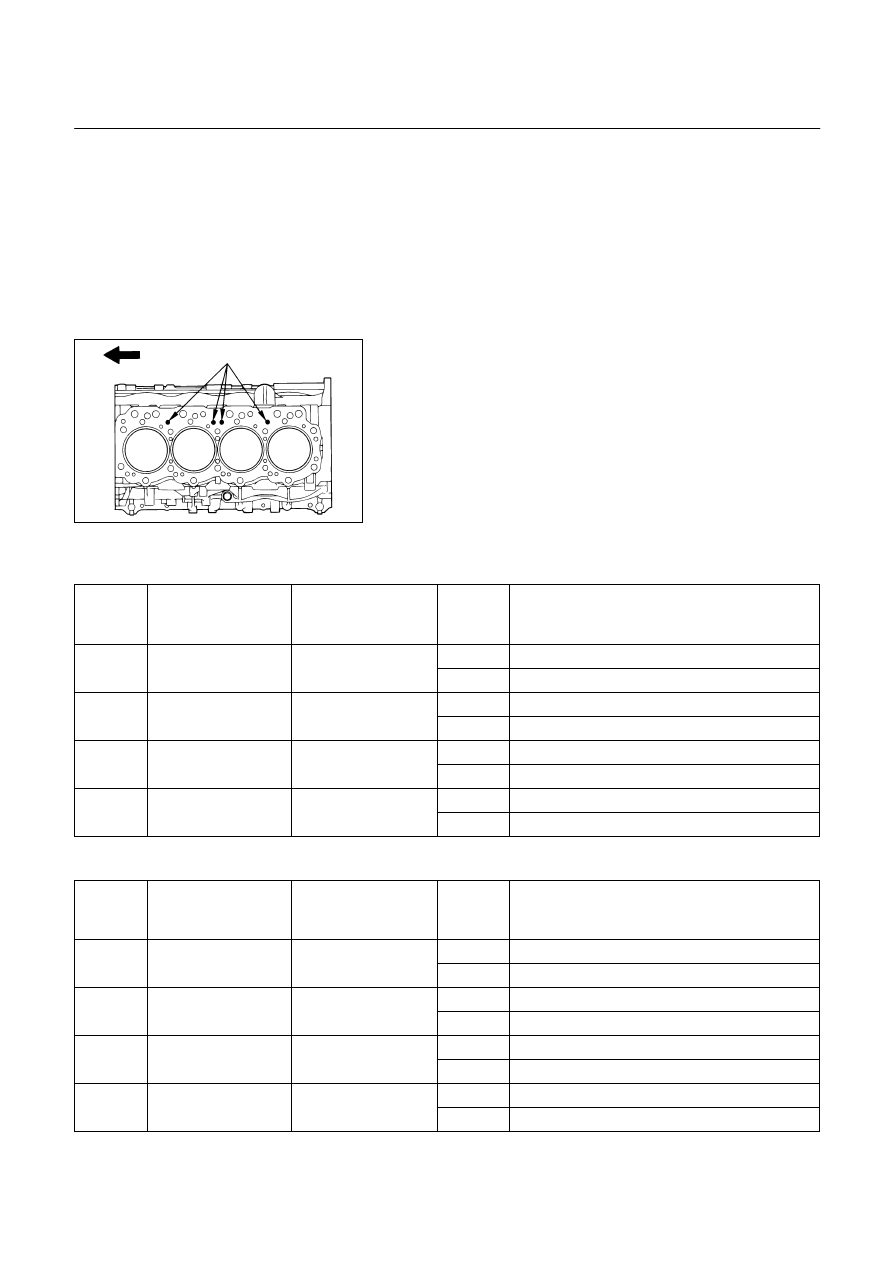
Cylinder Body Bore Measurement
1. Take measurements at measuring point
Q
across
positions
Q
-
Q
,
R
-
R
,
S
-
S
, and
T
-
T
.
Measuring Point
Q
98 mm (3.86 in)
2. Calculate the average value of the four measurements
to determine the correct cylinder grade.
3. Consult the following table with the resultant diameter
for the correct liner application.
6A – 88 ENGINE MECHANICAL
Cylinder Liner Grade Selection and Standard
Fitting Interference
Accurately measured fitting interference and proper
cylinder liner grade selection are extremely important.
If the cylinder liner fitting interference is too small, engine
cooling efficiency will be adversely affected.
If the cylinder liner fitting interference is too large, it will be
difficult to insert the cylinder liner into the cylinder body.
A mark was stamped on the upper of the cylinder block
during production to indicate the correct liner.
The liner grade (i.e.1.2.3.4) is indicated in metal stamp.
Cylinder Liner Grade
4JA1, 4JA1T, 4JB1T, 4JA1TC
mm (in)
Liner
Outside
Grade
Cylinder Body
Bore Diameter
Liner Outside
Diameter
Liner
Bore
Grade
Service Liner Bore Measurement
AX
93.035 – 93.050 (3.6628 – 3.6634)
1
95.001 – 95.010
(3.7402 – 3.7405)
95.011 – 95.020
(3.7406 – 3.7409)
CX
93.051 – 93.066 (3.6634 – 3.6640)
AX
93.035 – 93.050 (3.6628 – 3.6634)
2
95.011 – 95.020
(3.7406 – 3.7409)
95.021 – 95.030
(3.7410 – 3.7413)
CX
93.051 – 93.066 (3.6634 – 3.6640)
AX
93.035 – 93.050 (3.6628 – 3.6634)
3
95.021 – 95.030
(3.7410 – 3.7413)
95.031 – 95.040
(3.7414 – 3.7417)
CX
93.051 – 93.066 (3.6634 – 3.6640)
AX
93.035 – 93.050 (3.6628 – 3.6634)
4
95.031 – 95.040
(3.7414 – 3.7417)
95.041 – 95.050
(3.7418 – 3.7421)
CX
93.051 – 93.066 (3.6634 – 3.6640)
4JG2T, 4JH1TC
mm (in)
Liner
Outside
Grade
Cylinder Body
Bore Diameter
Liner Outside
Diameter
Liner
Bore
Grade
Service Liner Bore Measurement
AX
95.435 – 95.450 (3.7573 – 3.7579)
1
97.001 – 97.010
(3.8189 – 3.8193)
97.011 – 97.020
(3.8193 – 3.8197)
CX
95.451 – 95.466 (3.7579 – 3.7585)
AX
95.435 – 95.450 (3.7573 – 3.7579)
2
97.011 – 97.020
(3.8193 – 3.8197)
97.021 – 97.030
(3.8197 – 3.8200)
CX
95.451 – 95.466 (3.7579 – 3.7585)
AX
95.435 – 95.450 (3.7573 – 3.7579)
3
97.021 – 97.030
(3.8197 – 3.8200)
97.031 – 97.040
(3.8200 – 3.8205)
CX
95.451 – 95.466 (3.7579 – 3.7585)
AX
95.435 – 95.450 (3.7573 – 3.7579)
4
97.031 – 97.040
(3.8200 – 3.8205)
97.041 – 97.050
(3.8205 – 3.8209)
CX
95.451 – 95.466 (3.7579 – 3.7585)
012RY00022
ENGINE MECHANICAL 6A – 89
Cylinder Liner Installation
1. Cylinder Liner Installation Using The Special Tool
1) Use new kerosene or diesel oil to thoroughly clean
the cylinder liners and bores.
2) Use compressed air to blow-dry the cylinder liner
and bore surfaces.
Note:
All foreign material must be carefully removed from
the cylinder liner and the cylinder bore before
installation.
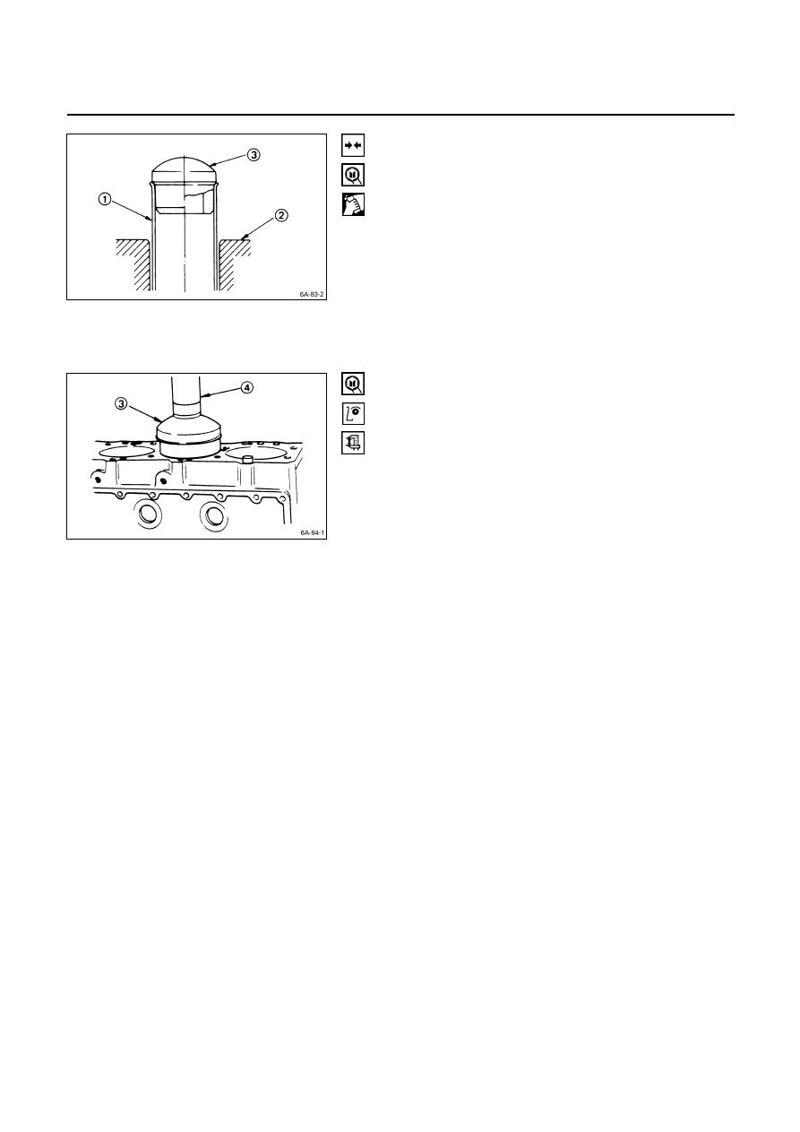
3) Insert the cylinder liner
Q
into the cylinder body
R
from the top of the cylinder body.
4) Set the cylinder liner installer
S
to the top of the
cylinder liner.
Cylinder
Liner
Installer:
5-8840-2040-0
5-8840-2313-0
(4JG2T,
4JH1TC)
5)
S
is directly beneath the bench press shaft center
T
.
Note:
Check that the cylinder liner is set perpendicular to
the bench press and that there is no wobble.
6) Use the bench press to apply a seating force of
500 kg (1,100 lb/4,900 N) to the cylinder liner.
7) Apply a force of 2,500 kg (5,500 lb/24,500 N) to
fully seat the cylinder liner.
8) After installing the cylinder liner, measure the
cylinder liner projection.
Refer to “Cylinder Liner Projection Inspection”.
2. Cylinder Liner Installation Using Dry Ice
Cylinder liner is a chrome plated dry type, it is
advisable to use dry ice during the installation
procedure.
Cooling the cylinder liner with dry ice will cause the
cylinder liner to contract, thus making installation
easier.
Note:
It is important that the cylinder liner be inserted to the
cylinder body immediately after it has been cooled.
Warning:
Dry ice must be used with great care. Careless
handling of dry ice can result in severe frostbite.
Нет комментариевНе стесняйтесь поделиться с нами вашим ценным мнением.
Текст