Isuzu D-Max / Isuzu Rodeo (TFR/TFS). Manual — part 1875
7A2-116 DIAGNOSIS
No. D1: Faulty Gear Shifting (Different from Shift Pattern)
Description:
•
Gear is shifted, different from the specified shift pattern.
Diagnosis Hints:
•
When inspecting faulty gear shifting, it is important to distinguish between the fault of electric system and
mechanical system (AT main unit).
•
Fault of electric system.
Monitor the output signal (each solenoid driving signal) using with Tech 2. If a trouble signal is sent to the
solenoid synchronously with the faulty gear shifting, the fault is originated in the electric system.
Monitor the input signal (signal from each sensor) using with Tech 2 and find an input signal by which the output
signal (each solenoid driving signal) is subjected to fault.
Fault of the electric system may be derived from temperature or vibration. For instance, though the engine is
normal while it is cold, fault may occur when the engine is warmed up or vehicle is running.
•
Fault of mechanical system.
If the gear is incorrectly shifted irrespective of operating signal (ON-OFF) of each solenoid, the faulty is
originated from the machine system (AT).
If the clutch slips, ATF smells burnt, contaminated to be black or the stall speed increases.
Possible Cause:
•
Disordered select cable.
•
Disordered inhibitor switch.
•
Slip
of
clutch.
If slip of clutch is caused, a DTC (gear ratio error) is stored.
•
Fixing at 3rd position (fail-safe activated)
Since the gear is fixed at the 3rd position because of the fail-safe function, a trouble that "Faulty gear
shifting" is resulted. In this case, the DTC is memorized.
When TCM stops operation because of faulty TCM ground, the gear is fixed at the 3rd position because
of a mechanical reason. In this case, no DTC is memorized.
••••
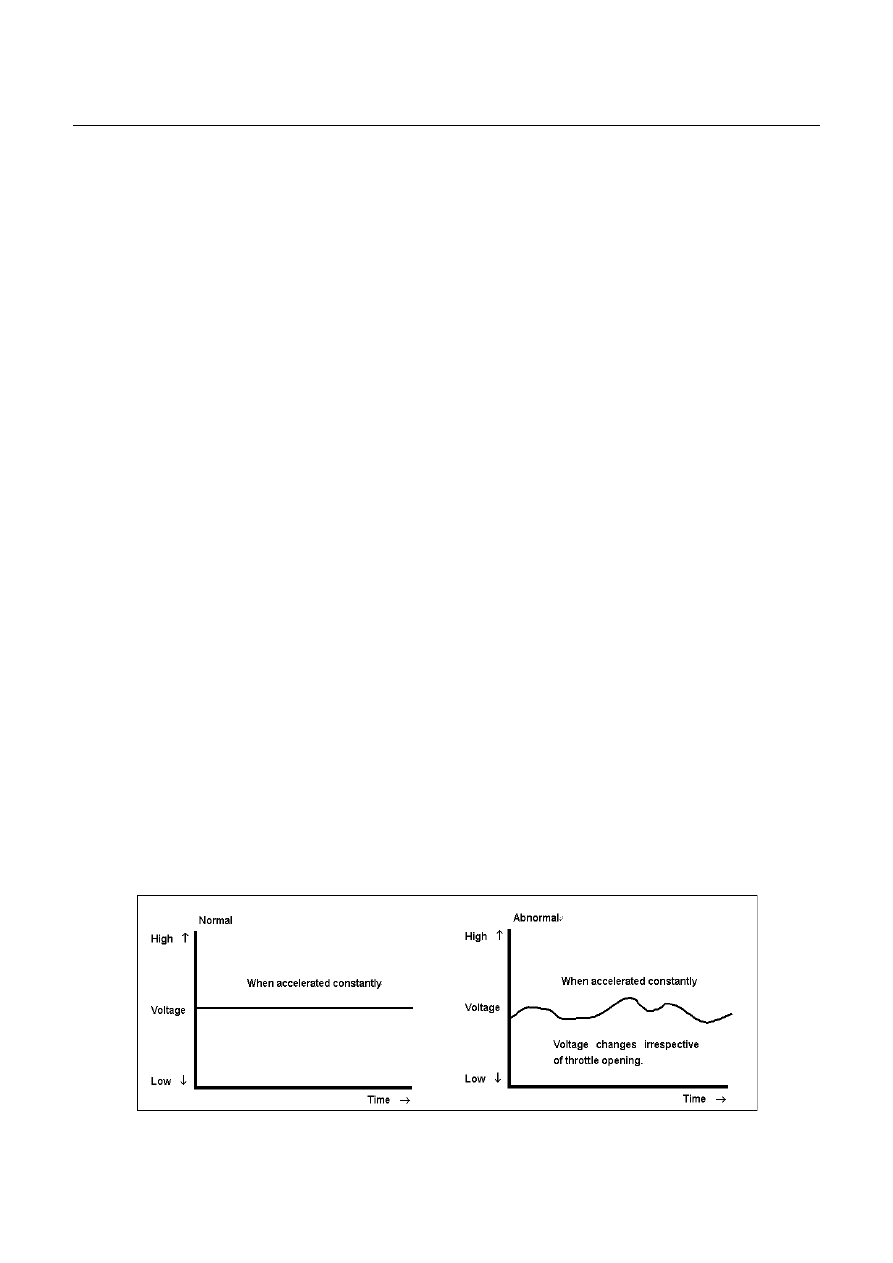
Incorrect properties of throttle opening signal (serial communication) of throttle position sensor.
The throttle opening signal which is sent by serial communication from ECM and TCM is an important
signal for gear shifting. In case of ECM fault or when the throttle position sensor does not issue voltage
signal according to the throttle opening, the gear is not shifted by stepping over the accelerator.
If the output voltage of the throttle position sensor changes freely even though the throttle opening is
constant, the gear is shifted incorrectly.
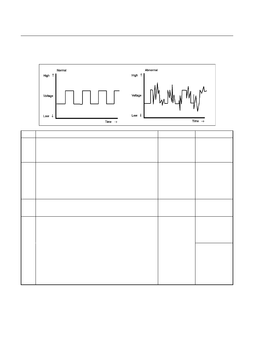
•
Faulty speed sensor.
DIAGNOSIS 7A2-117
When signal from the speed sensor becomes out of order, it may be judged a result of changed vehicle
speed and faulty gear shifting may be the causes.
••••
Trouble in control valve body (faulty operation, sticking, clogged oil passage)
Step
Action
Yes
No
1
Dislocation or disordered of select lever.
Does the vehicle move when the brake is released in a position
other than the P range and the vehicle is pushed?
Go to Step 2
Adjust the select
cable.
2
Gear ratio trouble diagnosis.
Travel in the following sequence for about 7 seconds or more in
each range: Start in the L range (1st) to 2 range (2nd) to 3 range
(3rd) to D range (4th) (to detect the gear ratio trouble exactly, this
process should be carried out)
Go to Step 3
Go to Step 3
3
Are any DTCs stored?
Go to DTC Chart
Go to Step 4
4
Are the quantity, contamination and smell normal?
If the ATF level is
low, replenish up to
the specified level.
Go to Step 5
If ATF is extremely
black and
contaminated and
smells burnt, slip of
the clutch is
supposed.

7A2-118 DIAGNOSIS
Step
Action
Yes
No
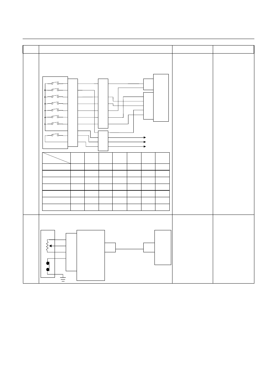
5
Inspection of electrical or mechanical fault
Is signal to each solenoid and pressure switch changed
synchronously to the faulty gear shift?
Control Valve
TCM
B1
B12
B20
RED/YEL
WHT/BLK
2-4 Brake Pressure SW
Terminal
Assembly
YEL
E54
(7)
(12)
(1)
H23
(12)
(10)
C95
(1)
(12)
(20)
RED/YEL
YEL
WHT/BLK
L&R Brake Pressure SW
High Clutch Pressure SW
H22
(8)
Control Valve
TCM
B6
B7
B8
B9
B22 (GND)
BLU/BLK
W HT/BLU
L&R Brake Solenoid
Terminal
Assembly
BLK/YEL
RED
2-4 Brake Solenoid
High Clutch Solenoid
Low Clutch Solenoid
E54
(5)
(9)
(10)
(3)
(11)
H23
(11)
(5)
(7)
(2)
(1)
GRY/RED
C95
(6)
(7)
(8)
(9)
(22)
BLU/BLK
BLK/YEL
RED
W HT/BLU
GRY/RED
Range
TCM terminal
Gear
B20
(High clutch
pressure SW)
B1
(2-4 brake pressure
SW)
B12 (Low & reverse
brake pressure SW)
P
-
More than 10V
More than 10V
More than 10V
R
Reverse
More than 10V
More than 10V
-
N
-
More than 10V
More than 10V
More than 10V
D, 3, 2
1st
More than 10V
More than 10V
More than 10V
2nd
More than 10V
-
More than 10V
3rd
-
More than 10V
More than 10V
4th
-
-
More than 10V
L
1st
More than 10V
More than 10V
-
2nd
More than 10V
-
More than 10V
3rd
-
More than 10V
More than 10V
4th
-
-
More than 10V
R a n g e
T C M te rm in a l
G e a r
B 8
(H ig h c lu tc h
s o le n o id )
B 9
(L o w c lu tch
s o le n o id )
B 7
(2 -4 b ra k e
s o le n o id )
B 6
(L o w & re v e rs e
b ra k e s o le n o id )
P
-
A p p ro x . 6 .8 V
(A C ra n g e )
-
A p p ro x . 6 .8 V
(A C ra n g e )
A p p ro x . 6 .2 V
(A C ra n g e )
R
R e v e rs e
A p p ro x . 6 .8 V
(A C ra n g e )
-
A p p ro x . 6 .8 V
(A C ra n g e )
-
N
-
A p p ro x . 6 .8 V
(A C ra n g e )
-
A p p ro x . 6 .8 V
(A C ra n g e )
A p p ro x . 6 .8 V
(A C ra n g e )
D , 3 , 2
1 s t
A p p ro x . 6 .8 V
(A C ra n g e )
-
A p p ro x . 6 .8 V
(A C ra n g e )
A p p ro x . 6 .8 V
(A C ra n g e )
2 n d
A p p ro x . 6 .8 V
(A C ra n g e )
-
-
A p p ro x . 6 .8 V
(A C ra n g e )
3 rd
-
-
A p p ro x . 6 .8 V
(A C ra n g e )
A p p ro x . 6 .8 V
(A C ra n g e )
4 th
-
A p p ro x . 6 .8 V
(A C ra n g e )
-
A p p ro x . 6 .8 V
(A C ra n g e )
L
1 s t
A p p ro x . 6 .8 V
(A C ra n g e )
-
A p p ro x . 6 .8 V
(A C ra n g e )
-
2 n d
A p p ro x . 6 .8 V
(A C ra n g e )
-
-
A p p ro x . 6 .8 V
(A C ra n g e )
3 rd
-
-
A p p ro x . 6 .8 V
(A C ra n g e )
A p p ro x . 6 .8 V
(A C ra n g e )
4 th
-
A p p ro x . 6 .8 V
(A C ra n g e )
-
A p p ro x . 6 .8 V
(A C ra n g e )
Go to Step 6
In case of fault in
the machine
system, repair that
portion or replace
the unit.
Slip of clutch or fault
of control valve.
DIAGNOSIS 7A2-119
Step
Action
Yes
No
6
Inspection of inhibitor switch using a Tech 2 or circuit tester.
Inspect the output voltage and throttle opening signal of the
throttle position sensor using a Tech 2 or circuit tester.
Inhibitor SW
TCM
A2 (P)
A17 (3)
B2 (2)
B10 (N)
B11 (D)
B19 (R)
B21 (L)
C95
(2)
(10)
(11)
(19)
(21)
YEL/VIO
RED/BLK
BLU
BLK/GRN
Starter Relay
C94
(2)
(3)
B
H22
(1)
(6)
(4)
(7)
(5)
(2)
P
2
R
N
D
3
L
Start SW
PNK/BLU
E51
(2)
(4)
(8)
(5)
(1)
(9)
(6)
(3)
(10)
(7)
(38)
(15)
(3)
(37)
H4
PNK/BLK
RED/YEL
YEL/VIO
BLK/GRN
PNK/BLK
RED/BLK
BLU
RED/YEL
PNK/BLU
BLK/WHT
BLK
BLK
BLK/WHT
Key Switch
WHT
WHT
Immobiliser Control Unit
TCM terminal
Range
A2
B19
B10
B11
B17
B2
B21
P
Battery
voltage
-
-
-
-
-
-
R
-
Battery
voltage
-
-
-
-
-
N
-
-
Battery
voltage
-
-
-
-
D
-
-
-
Battery
voltage
-
-
-
3
-
-
-
-
Battery
voltage
-
-
2
-
-
-
-
-
Battery
voltage
-
L
-
-
-
-
-
-
Battery
voltage
Go to Step 7
Adjust the inhibitor
switch.
7
Is a voltage value in proportion to the throttle opening output?
TPS
TCM
A16
C56
(28)
C94
(16)
RED/WHT
C56
(49)
(38)
(57)
(69)
ECM
A47 (GND)
A35 (Output)
A26
A55 (+5V)
A69 (Idle SW)
Go to Step 8
Repair the defect or
replace.
Нет комментариевНе стесняйтесь поделиться с нами вашим ценным мнением.
Текст