Isuzu D-Max / Isuzu Rodeo (TFR/TFS). Manual — part 1818
MSG MODEL (4WD) 7B-49
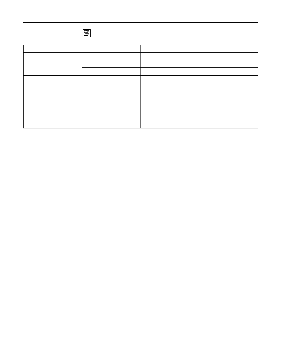
RECOMMENDED LIQUID GASKET
Type
Brand Name
Manufacturer
Remarks
ThreeBond 1207B
Three Bond
For Engine and
RTV* Silicon Base
ThreeBond 1207C
Three Bond
Transmission Repairs
ThreeBond 1215
Three Bond
For Axle Case Repairs
Water Base
ThreeBond 1141E
Three Bond
For Engine Repairs
ThreeBond 1104
Three Bond
BelcoBond 4
Isuzu
BelcoBond 401
Isuzu
BelcoBond 402
Isuzu
LOCTITE 515
Loctite
LOCTITE 518
Loctite
*RTV : Room Temperature Vulcanizer
Note:
1. It is very important that the liquid gaskets listed above or their exact equivalent be used on the vehicle.
2. Be careful to use the specified amount of liquid gasket.
Follow the manufacturer's instructions at all times.
3. Be absolutely sure to remove all lubricants and moisture from the connecting surfaces before applying
the liquid gasket.
The connecting surfaces must be perfectly dry.
4. LOTITE 515 and LOCTITE518 harden upon contact with a metal surface.
Do not apply LOTITE 515 or LOTITE 518 between two metal surfaces having a clearance of greater than
0.25 mm (0.01 in). Poor adhesion will result.
For Engine Repairs
Solvent
All
Anerobic
7B-50 MSG MODEL (4WD)
REMOVAL AND INSTALLATION
Read this Section carefully before performing any removal and installation procedure. This Section gives you
important points as well as the order of operation. Be sure that you understand everything in this Section before you
begin.
Important Operations - Removal
Battery Cable
Disconnect the negative (-) cable from the battery terminal.
Engine Hood
Apply setting marks to the engine hood and the engine hood
hinges before removing the engine hood.
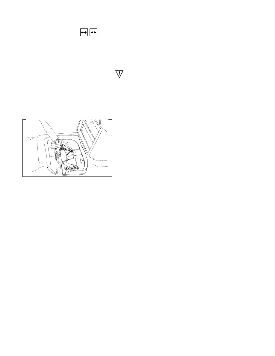
Gear Shift Lever and Transfer Change Lever
1. Place the gear shift lever in the neutral position.
2. Place the transfer change lever in the "H" position.
3. Remove the gear shift lever knob and transfer change lever
knob.
4. Remove the center console assembly and front console
assembly.
5. Remove the grommet and dust cover.
6. Remove the gear shift lever cover bolt.
7. Remove the gear shift lever.
8. Remove the transfer change lever retainer bolts.
9. Remove the transfer change lever and O-ring.
Note:
Cover the shift lever and change lever holes to prevent the
entry of foreign material into the transmission.
Lifting the Vehicle
1. Jack up the vehicle.
2. Place chassis stands at the front and the rear of the vehicle.
Transfer Case Protector
Remove the transfer case protector from the transmission
mounting member and the side menber.

MSG MODEL (4WD) 7B-51
Transmission and Transfer Case Oil Draining
1. Remove the transmission oil drain plug.
2. Replace the drain plug after draining the oil.
Exhaust Pipe
1. Remove the front exhaust pipe.
Rear Propeller Shaft (Single Shaft Type)
1. Remove the propeller shaft flange yoke at the drive pinion
side
1
.
2. Remove the propeller shaft from the transmission main
shaft spline
2
.
Rear Propeller shaft (Dual Shaft Type)
1. Apply setting marks to the 2nd propeller shaft flange yoke.
This will prevent mispositioning during the installation
procedure.
2. Remove the 2nd propeller shaft flange yoke bolts at the
drive pinion side
1
.
3. Remove the center bearing retainer bolts
2
.
4. Remove the 1st propeller shaft
3
with the center bearing
and the 2nd propeller shaft.
Pull the 1st propeller shaft toward the rear of the vehicle
until the spline yoke is free of the transmission main shaft.

7B-52 MSG MODEL (4WD)
Front Propeller Shaft
Remove the splined yoke flange bolt at the transfer case side.
Do not allow the splined yoke to fall sway from the front
Propeller shaft.
Important
Apply setting marks to the splined yoke and the propeller shaft
before removing the front propeller shaft.
If the splined yoke should fall away from the front propeller
shaft, align the setting marks
3
on the splined yoke
1
and the
propeller shaft
2
to reassemble the two parts.
Harness Connector
Disconnect the 4WD swich connectors, back up light switch
connector and the speedometer sensor connector.
Slave Cylinder
Remove the slave cylinder from the transmission case.
Engine Lifting Hanger
1. Attach the engine lifting hanger to the front portion of the
engine.
2. Attach the lifting wire to both ends of the engine lifting
hanger.
Нет комментариевНе стесняйтесь поделиться с нами вашим ценным мнением.
Текст