Isuzu D-Max / Isuzu Rodeo (TFR/TFS). Manual — part 1819
MSG MODEL (4WD) 7B-53
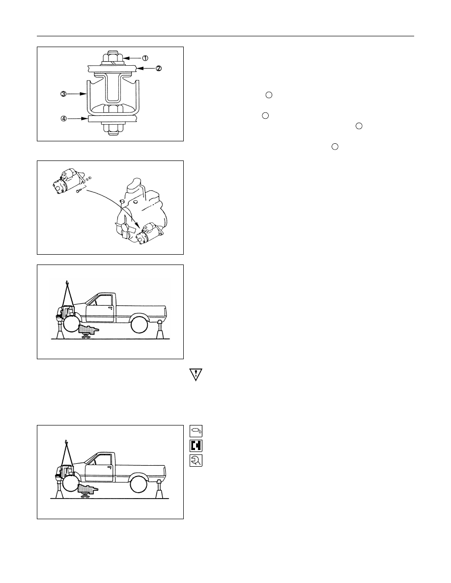
Engine Rear Mounting and Crossmember
1. Support the transmission with a transmission jack.
2. Remove No.2 crossmember.
3. Remove the engine rear mounting nuts from No.3
crossmember
3
.
4. Remove the engine rear mounting bolts from the
transmission
1
.
5. Remove No.3 crossmember and bolts
3
from the side
frame.
6. Remove the engine rear mounting
2
.
Starter Motor
Remove the starter motor from the engine real plate.
Transmission with Transfer
1. Remove the transmission nuts and bolts from the engine
rear plate.
2. Carefully pull the transmission with the transmission jack
toward the rear of the vehicle.
3. Operate the transmission jack to slowly lower the
transmission.
Important Operations - Installation
Follow the removal procedure in the reverse order to perform
the installation procedure.
Pay careful attention to the important points during the
installation procedure.
Transmission with Transfer
1. Apply a thin coat of molybdenum disulfide grease to the top
gear shaft spline.
2. Place the transmission on a transmission jack.
3. Carefully move the transmission jack and transmission into
position behind the cab.
7B-54 MSG MODEL (4WD)
4. Slowly raise the transsmission jack until the front of the
transmission is aligned with the rear of the engine.
The slope of the engine and the transmission must be the
same.
5. Align the top gear shaft spline with the clutch driven plate
internal spline.
6. Install the transmission to the engine.
Tighten the transmission nuts and bolt to the specified
torque.
Transmission Nut and Bolt Torque
N
⋅m (kgf⋅m/lb⋅ft)
M10 : 40
± 10 (4.1 ± 1.0 / 30 ± 7.2)
M12: 78
± 16 (8.0 ± 1.6 / 58 ± 12)
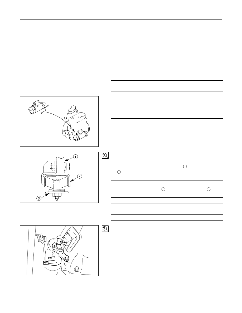
Starter Motor
Install the starter motor to the engine rear plate.
Starter Motor Bolt Torque
N
⋅m (kgf⋅m/lb⋅ft)
78
± 16 (8.0 ± 1.6 / 58 ± 12)
Engine Rear Crossmember and Mounting
Member
1. Install the engine rear crossmember
2
to the transmission
1
.
Rear Mounting Bolt Torque
N
⋅m(kgf⋅m/lb⋅ft)
83.3
± 4.9 (8.5 ± 0.5 / 61.5 ± 3.6)
2. Install the cross member
3
to the mounting rubber
2
.
Mounting Rubber Nut Torque
N
⋅m(kgf⋅m/lb⋅ft)
41
± 4.9 (4.2 ± 0.5 / 30 ± 3.6)
3. Install the cross member to the sideframe.
Mounting Member Bolt Torque
N
⋅m(kgf⋅m/lb⋅ft)
36.8
± 9.8 (3.8 ± 1.0 / 27.1 ± 7.2)
Slave Cylinder
Install the slave cylinder to the transmission case.
Slave Cylinder Bolt Torque
N
⋅m(kgf⋅m/lb⋅ft)
78
± 16 (8.0 ± 1.6 / 58 ± 12)

MSG MODEL (4WD) 7B-55
Harness Connector
Connect the 4WD switch connector, back up light switch
connector and speedometor sensor connector.
Front Propeller Shaft
1. Connect the propeller shaft flange yoke to the matching
flange.
2. Tighten the propeller shaft flange yoke bolt to the specified
torque.
Propeller Shaft Flange Yoke Bolt Torque
N
⋅m(kgf⋅m/lb⋅ft)
62.7
± 3.92 (6.4 ± 0.4 / 46.3 ± 2.90)
Note:
If the splined yoke and the front propeller shaft have
accidentally separated, align their setting marks and
recouple them.
Refer to "FRONT PROPELER SHAFT REMOVAL".
Rear Propeller Shaft (Single Shaft Type)
1. Insert the splined yoke
1
with the propeller shaft into the
transmission main shaft spline
2
.
2. Install the propeller shaft flange yoke
3
to the drive pinion
side.
3. Tighten the propeller shaft flange yoke bolt to the specified
torque.
Propeller Shaft Flange Yoke Bolt Torque
N
⋅m(kgf⋅m/lb⋅ft)
M8 : 35.3
± 2.94 (3.6 ± 0.3 / 26.0 ± 2.2)
M10 : 62.7
± 3.9 (6.4 ± 0.4 / 46.3 ± 2.9)
Rear Propeller Shaft (Dual Shaft Type)
1. Place the center bearing
1
together with the 1st peopeller
shaft
2
and 2nd propeller shaft
7
on the No.4
crossmember
3
.
2. Insert the splined yoke
4
into the transmission main shaft
spline
5
.
3. Tighten the center bearing retainer bolts
6
to the specified
torque.
Center Bearing Retainer Bolt Torque
N
⋅m(kgf⋅m/lb⋅ft)
60.8
± 11.8 (6.2 ± 1.2 / 44.8 ± 8.7)
4. Connect the 2nd propeller shaft
7
and drive pinion side
8
.
Be sure to align the setting marks applied at disassembly.
5. Tighten the coupling bolts to the specified torque.
Propeller Shaft Flange Yoke Bolt
Torque
N
⋅m(kgf⋅m/lb⋅ft)
M10 : 35.3
± 2.94 (3.6 ± 0.3 / 26.0 ± 2.2)
M12 : 62.7
± 3.9 (6.4 ± 0.4 / 46.3 ± 2.9)

7B-56 MSG MODEL (4WD)
Exhaust Pipe
1. Install the 2nd exhaust pipe.
Transfer Case Protector
1. Install the transfer case protector
1
to the mounting
member
2
and the sidemembers
3
.
2. Tighten the transfer case protector bolts to the specified
torque.
Transfer Case Protector Bolt Torque
N
⋅m(kgf⋅m/lb⋅ft)
36.3
± 9.8 (3.7 ± 1.0 / 26.8 ± 7.2)
Gear Shift Lever and Transfer Change
Lever
1. Replenish the transmission case and the transfer case with
the specified engine oil.
Transmission and Transfer Case Oil
lit (US gal.)
4.4 (1.16)
2. Install the gear shift lever to the gear control box.
Shift Lever Cover Torque
N
⋅m(kgf⋅m/lb⋅ft)
19.6
± 1.96 (2.0 ± 0.2 / 14.5 ± 1.5)
3. Install the dust cover.
4. Insert the transfer change lever to the transfer case.
Change Lever Retainer Bolt Torque
N
⋅m(kgf⋅m/lb⋅ft)
19.6
± 1.96 (2.0 ± 0.2 / 14.5 ± 1.5)
5. Install the grommet
6. Install the front console assembly and center console
assembly.
7. Install the gear shift lever and the transfer change lever
knobs.
Нет комментариевНе стесняйтесь поделиться с нами вашим ценным мнением.
Текст