Isuzu D-Max / Isuzu Rodeo (TFR/TFS). Manual — part 188
6E–356
4JH1 ENGINE DRIVEABILITY AND EMISSIONS
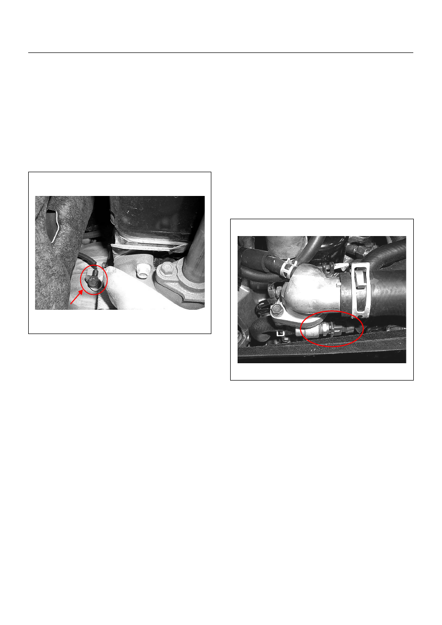
CRANKSHAFT POSITION (CKP)
SENSOR
Location
Installed to the clutch housing.
Removal Procedure
1. Disconnect the negative battery cable.
2. Disconnect connector from the CKP sensor.
3. Loosen a bolt and remove the CKP sensor from the
clutch housing.
Installation Procedure
1. Install the CKP sensor to the clutch housing.
2. Tighten CKP sensor by a bolt with specified
tightening torque.
Tightening Torque
• Bolts: 8.0 - 12.0 N·m (0.8 - 1.2 kgf·m)
3. Connect a CKP sensor connector to the CKP
sensor.
4. Connect the negative battery cable.
NOTE: Verify any DTCs (diagnosis Trouble Code) are
not stored after replacement.
ENGINE COOLANT TEMPERATURE
(ECT) SENSOR
Location
Installed to the thermostat housing.
Removal Procedure
1. Disconnect the negative battery cable.
2. Drain enough engine coolant so that the coolant
level will be below the ECT sensor.
3. Disconnect connector from the ECT sensor.
4. Loosen and remove the ECT sensor from the
thermostat housing.
NOTE: Cool down the engine before above procedures
are carried out.
Installation Procedure
1. Apply sealer to threads of screw at the ECT sensor.
2. Tighten the ECT sensor with specified tightening
torque.
Tightening Torque
• Bolt: 13N·m (1.3kgf·m)
3. Connect a ECT sensor connector to the ECT
sensor.
4. Fill the engine coolant.
5. Connect the negative battery cable.
NOTE: Verify any DTCs (diagnosis Trouble Code) are
not stored after replacement.
Verify no engine coolant leaking from the sensor
threads after replacement.
4JH1 ENGINE DRIVEABILITY AND EMISSIONS
6E–357
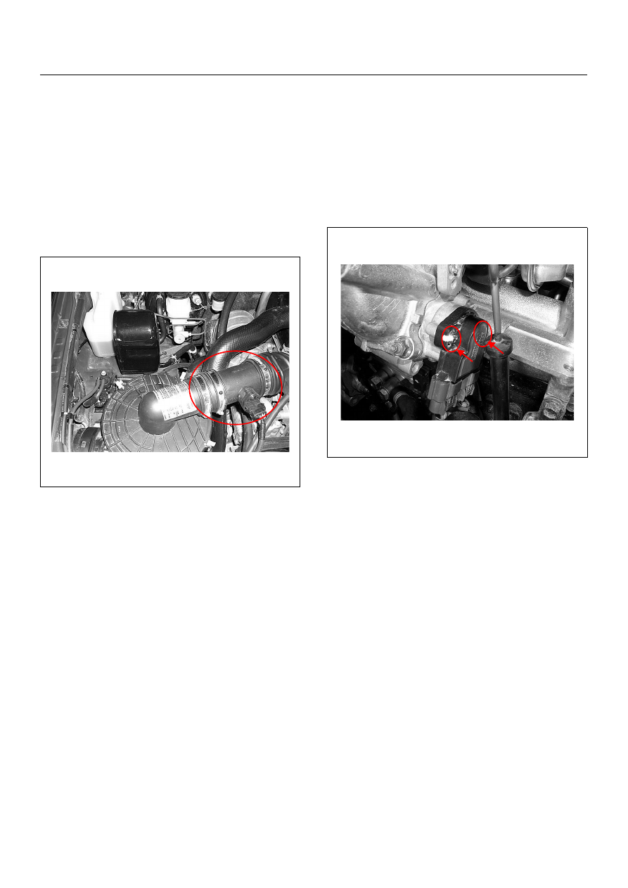
MASS AIR FLOW (MAF) & INTAKE
AIR TEMPERATURE (IAT) SENSOR
Location
Installed to the intake duct housing.
Removal Procedure
1. Disconnect the negative battery cable.
2. Disconnect a MAF & IAT sensor connector from the
MAF & IAT sensor assembly.
3. Loosen the clips and remove the MAF & IAT sensor
assembly from the intake duct housing.
Installation Procedure
1. Install the MAF & IAT sensor assembly into intake
air duct.
2. Tighten the clips.
3. Connect a MAF & IAT sensor connector to the MAF
& IAT sensor assembly.
4. Connect the negative battery cable.
NOTE: Verify any DTCs (diagnosis Trouble Code) are
not stored after replacement.
THROTTLE POSITION SENSOR (TPS)
Location
Installed on the throttle body.
Removal Procedure
1. Disconnect the negative battery cable.
2. Disconnect the TPS connector.
3. Loosen two screws and remove TPS from the
throttle body.
Installation Procedure
1. Temporary tighten the TPS by two screws.
2. Connect a TPS connectors to the TPS.
3. Connect the Tech2 to the vehicle.
4. Connect the negative battery cable.
5. Select “Data Display” with the Tech2.
6. Check the throttle position data and adjust the TPS
position.
7. Tighten two screws.
NOTE: Verify any DTCs (diagnosis Trouble Code) are
not stored after replacement.
6E–358
4JH1 ENGINE DRIVEABILITY AND EMISSIONS
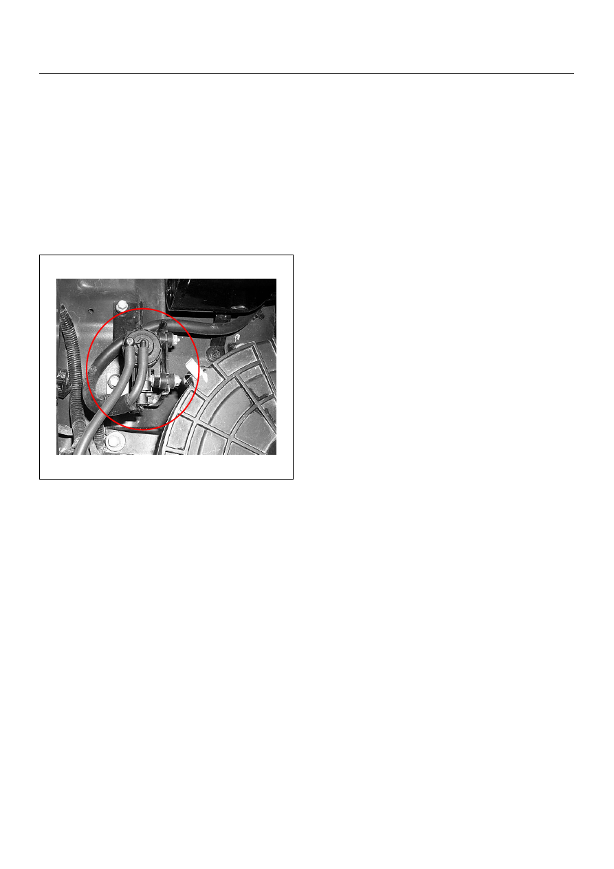
EGR EVRV (Electrical Vacuum
Regulating Valve)
Location
Back of the air cleaner case.
Removal Procedure
1. Disconenct the negative battery cable.
2. Disconnect a EVRV connector from the EVRV.
3. Disconnect two hoses from the EVRV.
4. Loosen two bolts and remove the EVRV from the
bracket.
Installation Procedure
1. Tighten the purge solenoid by tow bolts.
2. Connect a connector to the EVRV.
3. Connect two hoses to the EVRV.
4. Connect the negative battery cable.
NOTE: Verify any DTCs (diagnosis Trouble Code) are
not stored after replacement.
Verify proper connection of two hoses.
4JH1 ENGINE DRIVEABILITY AND EMISSIONS
6E–359
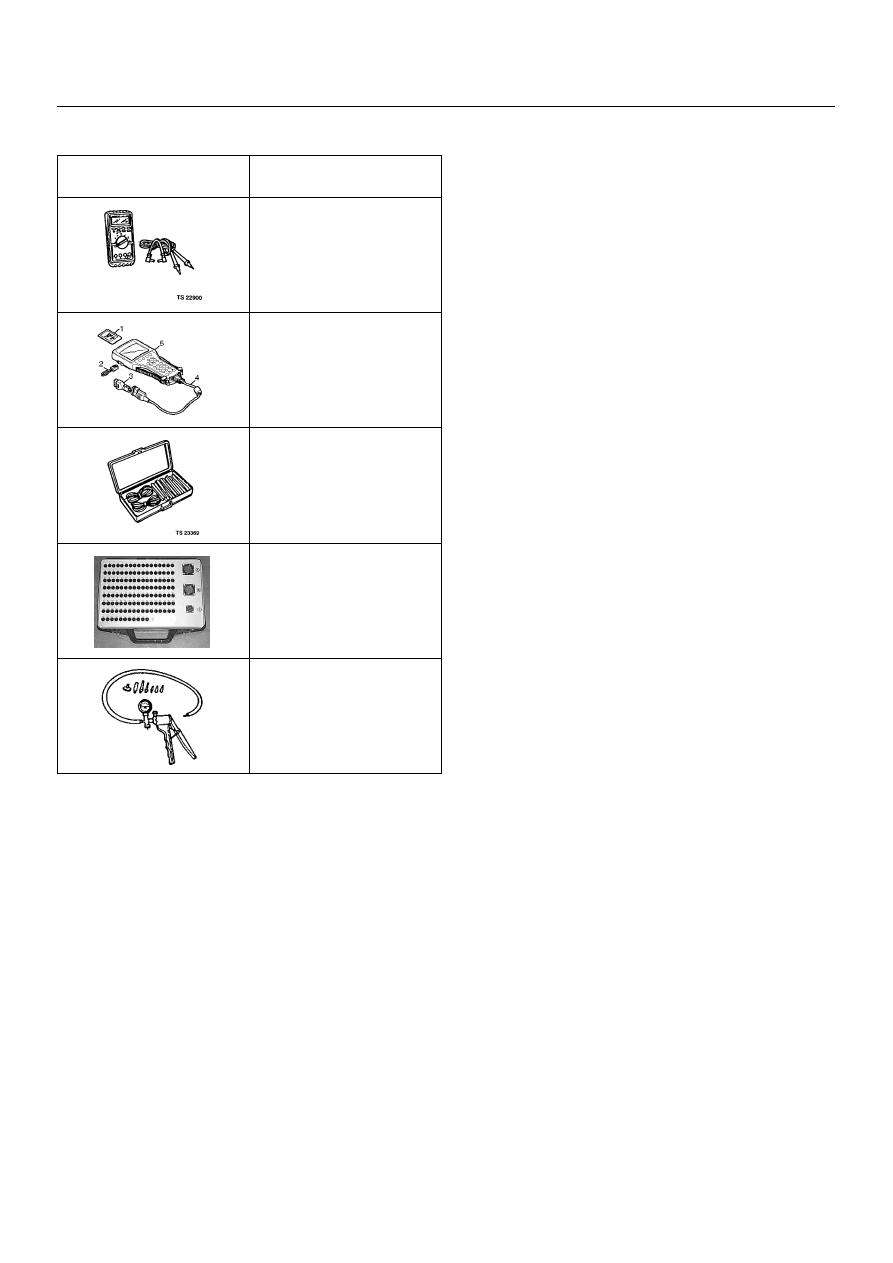
SPECIAL SERVICE TOOLS
ILLUSTRATION
TOOL NO.
TOLL NAME
5-8840-0285-0
(J 39200)
High Impedance
Multimeter
(Digital Voltmeter -DVM)
(1) PCMCIA Card
(2) RS232 Loop Back
Connector
(3) SAE 16/19 Adapter
(4) DLC Cable
(5) TECH 2
5-8840-0385-0
(J 35616-A/BT-8637)
Connector Test Adapter Kit
Breaker Box
5-8840-0279-0
(J 23738-A)
Vacuum Pump with Gauge
Нет комментариевНе стесняйтесь поделиться с нами вашим ценным мнением.
Текст