Isuzu D-Max / Isuzu Rodeo (TFR/TFS). Manual — part 187
6E–352
4JH1 ENGINE DRIVEABILITY AND EMISSIONS
10
Remove the MAF & IAT sensor assembly and check
for the following conditions.
• Objects blocking at the MAF sensor element.
If a problem is found, repair as necessary.
Was the problem found?
—
Verify repair
Go to Step 11
11
Check the MAF sensor harness for the following
conditions.
• Check for poor connector connection.
• Check for misrouted harness.
• Check for any accessory parts which may cause
electric interference.
If a problem is found, repair as necessary.
Was a problem found?
—
Verify repair
Go to Step 12
12
Substitute a known good MAF & IAT sensor assembly
and recheck.
Was the problem solved?
—
Go to Step 13
Go to Step 22
13
Replace the MAF & IAT sensor assembly.
Is the action complete?
—
Verify repair
—
14
1. Using the Tech 2 and ignition “On” and engine
“Run”.
2. Monitor the following parameters in the data
display.
• “Desired Injection Quantity” & “Injection Quantity”
• “Desired Injection Start” & “Actual Injection Start”
Are the large gap or unstable parameter displayed
between “Desired” and “Actual”?
—
Go to Step 21
Go to Step 15
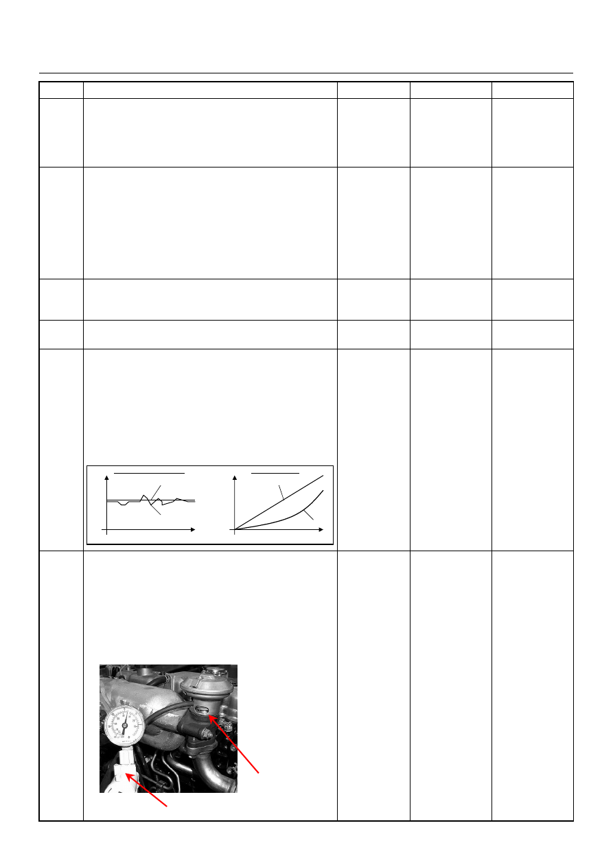
15
Using the vacuum pump and check the EGR valve (if
equipped) operation for the following condition through
the small window.
• Restrict shaft movement. Check for objects sticking
the shaft, broken diaphragm or excessive carbon
deposit.
If a problem is found, repair as necessary.
Was a problem found?
—
Verify repair
Go to Step 16
Step
Action
Value(s)
Yes
No
When idling or part-throttle When accelerated
High
Desired
Low
Time
Actual
High
Low
Desired
Actual
Time
Vacuum Pump
Small Window
4JH1 ENGINE DRIVEABILITY AND EMISSIONS
6E–353
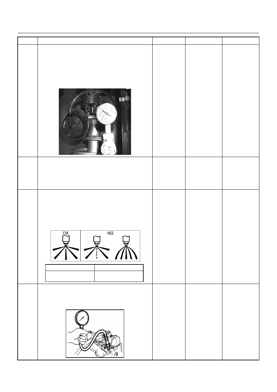
16
Using the vacuum pump and check the exhaust
throttle valve (if equipped) operation for the following
condition.
• Restrict shaft movement. Check for objects sticking
the shaft, broken diaphragm or excessive carbon
deposit.
Was a problem found?
—
Verify repair
Go to Step 17
17
Check the exhaust system for a possible restriction.
• Damaged or collapsed pipes or catalytic converter.
• Internal muffler failure.
If a problem is found, repair as necessary.
Was a problem found?
—
Verify repair
Go to Step 18
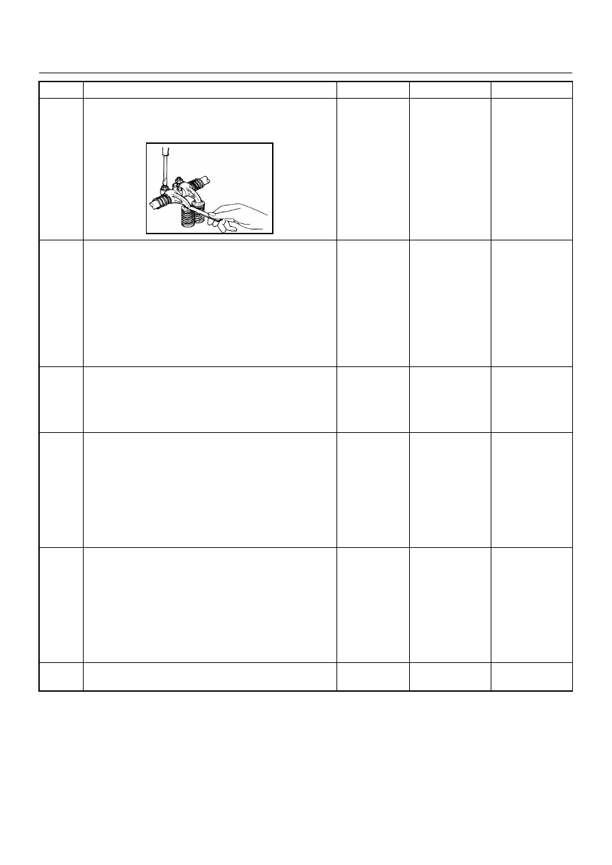
18
Remove the injection nozzles from the engine and
check for the following conditions.
• Improper splay condition.
• Operating pressure is incorrect.
If a problem is found, repair as necessary.
Was the problem found?
—
Replace the
injection nozzle
and verify repair
Go to Step 19
19
Check the engine compression pressure for each
cylinders.
If a problem is found, repair as necessary.
Was the problem found?
More than 30
Mpa (31.0 kg/
cm
2
)
Verify repair
Go to Step 20
Step
Action
Value(s)
Yes
No
1
st
Stage
2
nd
Stage
20.0 - 21.0 Mpa
(204 - 214 kg/cm
2
)
34.3 - 35.8 Mpa
(350 - 365 kg/cm
2
)
6E–354
4JH1 ENGINE DRIVEABILITY AND EMISSIONS
20
Check the inlet/exhaust valve clearance for each
valves.
Are the valve clearances within the specified value?
0.4mm at cold
(In/Ex)
Go to Step 21
Adjust and
verify repair
21
1. Review all diagnostic procedures within this table.
2. If all procedures have been completed and no
malfunctions have been found, review/inspect the
following:
• Visual/physical inspection
• Tech 2 data
• All electrical connections within a suspected circuit
and/or system
Was a problem found?
—
Verify repair
Go to Step 22
22
Is the ECM programmed with the latest software
release?
If not, download the latest software to the ECM using
the “SPS (Service Programming System)”.
Was the problem solved?
—
Verify repair
Go to Step 23
23
Substitute a known good ECM and recheck.
Was the problem solved?
IMPORTANT: The replacement ECM must be
programmed. Refer to section of the Service
Programming System (SPS) in this manual.
Following ECM programming, the immobiliser system
(if equipped) must be linked to the ECM. Refer to
section 11 “Immobiliser System-ECM replacement” for
the ECM/Immobiliser linking procedure.
—
Go to Step 24
Go to Step 25
24
Replace the ECM.
Is the action complete?
IMPORTANT: The replacement ECM must be
programmed. Refer to section of the Service
Programming System (SPS) in this manual.
Following ECM programming, the immobiliser system
(if equipped) must be linked to the ECM. Refer to
section 11 “Immobiliser System-ECM replacement” for
the ECM/Immobiliser linking procedure.
—
Verify repair
—
25
Replace the injection pump assembly.
Is the action complete?
—
Verify repair
—
Step
Action
Value(s)
Yes
No
4JH1 ENGINE DRIVEABILITY AND EMISSIONS
6E–355
ON-VEHICLE SERVICE PROCEDURE
ENGINE CONTROL MODULE
(ECM)
Location
Under the left-hand side seat.
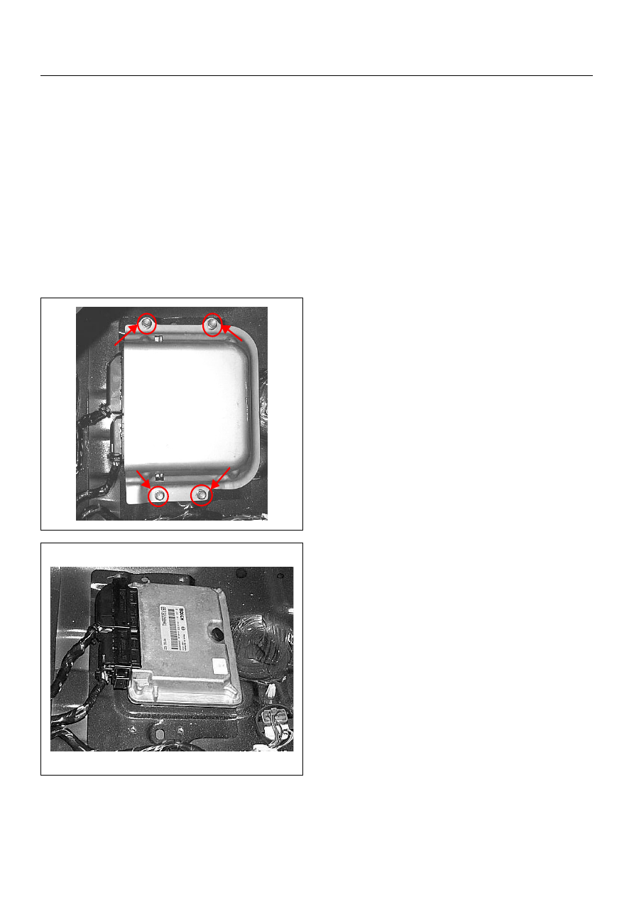
Removal Procedure
1. Disconnect the negative battery cable.
2. Remove the seat left-hand side.
3. Roll up the floor carpet.
4. Remove four bolts from the ECM cover.
5. Disconnect the two connectors from the ECM.
Installation Procedure
1. Connect the two connectors to the ECM.
2. Put on the ECM to the floor panel.
3. Tighten the ECM cover by four bolts with specified
tightening torque.
Tightening torque
• Bolts: 8.0 - 12.0 N·m (0.8 - 1.2 kgf·m)
4. Lay the floor carpet exactly.
5. Put on the seat to the floor panel and tighten with
specified tightening torque.
Tightening torque
• Bolts: 40.0 N·m (4.1 kgf·m)
6. Connect the negative battery cable.
NOTE: The replacement ECM must be programmed.
Refer to section of the Service Programming System
(SPS) in this manual.
Following ECM programming, the immobiliser system (if
equipped) must be linked to the ECM. Refer to section
11 “Immobiliser System-ECM replacement” for the
ECM/Immobiliser linking procedure.
Нет комментариевНе стесняйтесь поделиться с нами вашим ценным мнением.
Текст