Isuzu D-Max / Isuzu Rodeo (TFR/TFS). Manual — part 862
6E–177
3.2L ENGINE DRIVEABILITY AND EMISSIONS
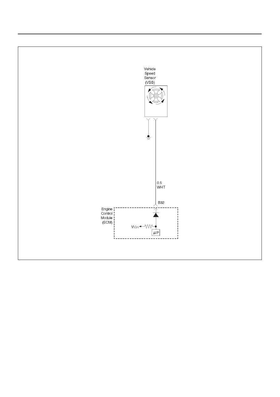
Diagnostic Trouble Code (DTC) P0502 (Flash DTC=24) VSS No Signal
060RW052
Circuit Description
The vehicle speed sensor has a magnet rotated by the
transmission output shaft. Attached to the sensor is a hall
effect circuit the interacts with the magnetic field treated
by the rotating magnet. A 12-volt operating supply for the
speed sensor hall circuit is supplied from the meter fuse.
The VSS pulses to ground the 9-volt signal sent from the
engine control module (ECM) on the reference circuit.
The ECM interprets vehicle speed by the number of
pulses to ground per second on the reference circuit.
Conditions for Setting the DTC
D
Engine is running.
D
Engine speed is below 5000 RPM.
D
Fuel is cutting.
D
Vehicle speed is below 1Km/H for more than 4 second.
Action Taken When the DTC Sets
D
The ECM will illuminate the malfunction indicator lamp
(MIL) the first time the fault is detected.
D
The ECM will store conditions which were present
when the DTC was set as Freeze Frame and in the
Failure Records data.
Conditions for Clearing the MIL/DTC
D
The ECM will turn the MIL “OFF” on the third
consecutive trip cycle during which the diagnostic has
been run and the fault condition is no longer present.
D
A history DTC P0502 will clear after 40 consecutive
warm-up cycles have occurred without a fault.
D
DTC P0502 can be cleared by using the Tech 2 “Clear
Info” function or by disconnecting the ECM battery
feed.

6E–178 3.2L ENGINE DRIVEABILITY AND EMISSIONS
Test Description
Number(s) below refer to the step number(s) on the
Diagnostic Chart.
9. To avoid backprobing the VSS and possibly
damaging a seal or terminal, the VSS output can be
tested at the point where the transmission harness
connected to the engine harness. The green 16-way
connector is adjacent to a blue 16-way connector,
and it can be easily accessed by removing the air
cleaner assembly. The green 16-way connector is
separated, and battery voltage is applied to the VSS
through the yellow wire at one corner of the
connector. The VSS output can be monitored with a
DVM connected to the blue wire with a black tracer.
The two wires are next to each other in the 16-way
connector . The test connections are made on the
transmission side of the connector, the side that is
not clipped to the body sheetmetal.
14. The speedometer-to-ECM VSS signal wire is
spliced to a wire leading to the cruise control
module. If a short to ground or voltage is found
between the ECM and speedometer, it could be
located between the splice and the cruise control
module.
DTC P0502 –VSS Circuit Low Input
Step
Action
Value(s)
Yes
No
1
Was the “On-Board Diagnostic (OBD) System Check”
performed?
—
Go to
Step 2
Go to
OBD
System
Check
2
Does the speedometer work?
—
Go to
Step 10
Go to
Step 3
3
1. Disconnect the VSS connector.
2. Ignition “ON.”
3. Using a test light to battery +, probe the connector
ground wire.
Did the light illuminate?
—
Go to
Step 5
Go to
Step 4
4
Repair the sensor ground.
Is the action complete?
—
Verify repair
—
5
1. Ignition “ON,” sensor disconnected.
2. Using a DVM, measure at the VSS connector
between ground and voltage supply.
Was the measurement near the specified value?
Battery
voltage
Go to
Step 7
Go to
Step 6
6
Repair the open or short to ground which may have
blown the meter fuse.
Is the action complete?
—
Verify repair
—
7
1. Ignition “ON,” VSS disconnected.
2. Using a DVM, measure at the VSS connector
between ground and the blue/black wire from the
speedometer.
Was the measurement near the specified value?
7.5-8 V
Go to
Step 9
Go to
Step 8
8
Check for an open or short circuit between the
speedometer and the VSS.
Was an open or short circuit located?
—
Verify repair
Go to
Step 9
9
Replace the speedometer.
Is the action complete?
—
Verify repair
—

6E–179
3.2L ENGINE DRIVEABILITY AND EMISSIONS
DTC P0502 –VSS Circuit Low Input
(Cont'd)
Step
No
Yes
Value(s)
Action
10
1. Ignition “OFF.”
2. Disconnect the MAF sensor and remove the air
cleaner assembly and filter element to gain access
to the 16-way green connector located immediately
to the rear of the left front headlamp. The connector
attaches the VSS wires from the transmission
harness to the left-side engine harness.
3. Disconnect the green 16-way connector.
4. Select a terminal adapter from kit 5-8840-0385-0
that can be used with a jumper to supply B+ to the
yellow (transmission side of the connector). There
are 2 yellow wires at that connector, but the correct
one is in the corner position.
5. Use another terminal adapter to attach a voltmeter
to the blue wire with a black tracer (next to the wire in
the previous step.)
6. At the transmission side of the green 16-way
connector, locate the black wire next to the VSS
yellow ign+ wire. The black wire is the VSS ground
wire. Use a terminal adapter to attach a jumper to
ground to the black VSS ground wire at the
transmission side of the connector.
7. Raise the rear wheels off the ground with
transmission in neutral.
Does the DVM toggle back and forth between 0.6 V and
10 V as the wheels (and driveshaft) are rotated?
—
Go to
Step 12
Go to
Step 11
11
Replace the VSS.
Is the action complete?
—
Verify repair
—
12
Check for an open or short between the ECM and the
speedometer.
Was a problem found?
—
Verify repair
Go to
Step 13
13
Replace the ECM.
Is the action complete?
—
Verify repair
—

6E–180 3.2L ENGINE DRIVEABILITY AND EMISSIONS
Diagnostic Trouble Code (DTC) P0562 (Flash DTC=66) System Voltage Low
Circuit Description
The engine control module (ECM) monitors the system
voltage on the ignition feed terminals to the ECM. A
system voltage DTC will set whenever the voltage is
above a calibrated value.
Conditions for Setting the DTC
D
Engine is running.
D
System voltage is below 6 volts for more than 20
second.
Action Taken When the DTC Sets
D
The ECM will not illuminate the malfunction indicator
lamp (MIL).
D
The ECM will store as Failure Records only conditions
which were present when the DTC was set. This
information will not be stored as Freeze Frame data.
Conditions for Clearing the MIL/DTC
D
A history DTC P0563 will clear after 40 consecutive
warm-up cycles have occurred without a fault.
D
DTC P0563 can be cleared by using the Tech 2 “Clear
Info” function or by disconnecting the ECM battery
feed.
Diagnostic Aids
If the DTC sets when an accessory is operated, check for
a poor connection or defective accessory.
DTC P0562 – System Voltage Low
Step
Action
Value(s)
Yes
No
1
Was the “On-Board Diagnostic (OBD) System Check”
performed?
—
Go to
Step 2
Go to
OBD
System
Check
2
Using a DVM, measure the battery voltage at the
battery.
Is the battery voltage greater than the specified value?
11.5 V
Go to
Step 3
Charge
battery, then
go to
Step 3
3
1. Install a Tech 2.
2. Select “Ignition Volts” on the Tech 2.
3. Start the engine and raise the engine speed to the
specified value.
4. Load the electrical system by turning on the
headlights, high blower, etc.
Is the ignition voltage approximately equal to the
specified value?
2000 RPM
12.8-14.1 V
Go to
Step 4
Go to
Starting/Char
ging
4
1. Ignition “OFF.”
2. Disconnect the ECM connector at the ECM.
3. Using a DVM, measure the battery voltage at the
ECM connector.
Is it approximately equal to battery voltage?
—
Check for
excessive
current draw
with ignition
“OFF,” engine
“OFF.”
Go to
Step 5
5
1. Check for faulty connections at the ECM harness
terminals.
2. Repair as necessary.
Was a repair necessary?
—
Verify repair
Go to
Step 6
6
Check for an open battery feed circuit to the ECM.
Is the action complete?
—
Verify repair
Go to
Step 7
7
Replace the ECM.
Is the action complete?
—
Verify repair
—
Нет комментариевНе стесняйтесь поделиться с нами вашим ценным мнением.
Текст