Isuzu D-Max / Isuzu Rodeo (TFR/TFS). Manual — part 1870

7A2-96 DIAGNOSIS
No. A3: Vehicle Does Not Run in D, 3, 2 and L Range
Description:
•
Vehicle does not run in D, 3, 2 and L range only.
•
It runs correctly in R ranges.
Diagnosis Hints:
•
Some trouble in the AT main unit is supposed (since the vehicle can run even if the TCM is defective). However,
since the trouble of the main unit may be originated from the sensor system or output system, these systems
should be also checked to prevent reproduce of the trouble.
Possible Cause:
•
Slip of clutch (low clutch and low one-way clutch).
If slip of clutch is caused, a DTC (gear ratio error) is stored.
•
Shortage or faulty quality of ATF.
•
Dropped line pressure.
•
Trouble in control valve body (faulty operation, sticking, clogged oil passage).
•
Disordered select cable (select indicator light indicates D, 3, 2 and L but the hydraulic system is not in the D, 3, 2
and L range).
•
Faulty torque generated.
•
Trouble in the torque converter (faulty operation, sticking), insufficient engine output.
•
Malfunction of parking mechanism.
Step
Action
Yes
No
1
Dislocation or disordered of select lever.
Does the vehicle move when the brake is released in a
position other than the P range and the vehicle is pushed?
Go to Step 2
Adjust the select cable.
2
Are any DTCs stored?
Go to DTC Chart
Go to Step 3
3
Are the quantity, contamination and smell normal?
If the ATF level is low,
replenish up to the
specified level.
Go to Step 4
If ATF is extremely
black and
contaminated and
smells burnt, slip of the
clutch is supposed.
Overhaul the AT unit.
4
Is the stall revolution correct in D, 3, 2 and L range? Refer
the STALL TEST section in this manual.
Go to Step 5
Repair the defect or
replace.
5
Is the line pressure correct? Refer the LINE PRESSURE
TEST section in this manual.
Trouble in the AT
assembly or control
valve.
Repair the defect or
replace.

DIAGNOSIS 7A2-97
No. B1: Vehicle Runs in N Range
Description:
•
Creep appears in N range.
•
Vehicle moves unless the brake pedal is stepped on in N range.
Diagnosis Hints:
•
Basically a trouble in the AT main unit. However, some trouble in the sensor system or output system may have
some influence on the trouble in the main unit and therefore these systems should be also checked to prevent
reproduce of the trouble.
Possible Cause:
•
Seized clutch (low clutch, low one-way clutch, reverse clutch, low & reverse brake).
•
Trouble in the control valve (faulty operation, sticking, clogged oil passage).
•
Dislocated select lever (the select indicator light indicates the N range but the hydraulic system is in the D, 3, 2
or L range).
Step
Action
Yes
No
1
Dislocation or disordered of select lever.
Does the vehicle move when the brake is released in a
position other than the P range and the vehicle is pushed?
Go to Step 2
Adjust the select cable.
2
Are any DTCs stored?
Go to DTC Chart
Go to Step 3
3
Are the quantity, contamination and smell normal?
If the ATF level is low,
replenish up to the
specified level.
Trouble in the AT
assembly or control
valve.
If ATF is extremely
black and
contaminated and
smells burnt, slip of the
clutch is supposed.
Overhaul the AT unit.

7A2-98 DIAGNOSIS
No. B2: Poor Acceleration at Starting
Description:
•
Starting acceleration is poor.
Diagnosis Hints:
•
In addition to the low engine output, faulty gear shifting of AT or fixing at the 3rd position may be possible.
Therefore, in case of such a trouble that "maximum speed is low, and acceleration is poor", it should be cleared
up whether the trouble is originated from the engine system of AT system by a running test, inspection of stall
revolution, etc.
Possible Cause:
•
Clogged air cleaner, out of injection timing, dropped compression pressure, etc.
•
Fixing at 3rd position (fail-safe activated).
Since the gear is fixed at the 3rd position because of the fail-safe function, a trouble that "Maximum
speed is low, and acceleration is poor" is resulted. In this case, the DTC is memorized.
When TCM stops operation because of faulty TCM ground, the gear is fixed at the 3rd position because
of a mechanical reason. In this case, no DTC is memorized.
•
Disordered inhibitor switch.
•
Incorrect properties of throttle opening signal (serial communication) of throttle position sensor.
Throttle opening signal (serial communication) of the throttle position sensor does not change in
proportion to the throttle opening. In this case, fixing at the high or low gear results in such a trouble
that "Maximum Speed is Low and Acceleration is Poor".
•
Slip of clutch (low clutch, high clutch).
•
If slip of clutch is caused, a DTC (gear ratio error) is stored.
•
Dropped line pressure.
•
Trouble in the torque converter system (faulty operation).
Step
Action
Yes
No
1
Test Drive.
Is the gear smoothly shifted in the order of 1st to 2nd, 2nd to 3rd,
3rd to 4th gear and lock up?
Clogged air cleaner,
out of injection
timing, dropped
compression
pressure, etc.
Go to Step 2
2
Gear ratio trouble diagnosis.
Travel in the following sequence for about 7 seconds or more in
each range: Start in the L range (1st) to 2 range (2nd) to 3 range
(3rd) to D range (4th) (to detect the gear ratio trouble exactly, this
process should be carried out)
Go to Step 3
Go to Step 3
3
Are any DTCs stored?
Go to DTC Chart
Go to Step 4
DIAGNOSIS 7A2-99
Step
Action
Yes
No
4
Are the quantity, contamination and smell normal?
If the ATF level is
low, replenish up to
the specified level.
Go to Step 5
If ATF is extremely
black and
contaminated and
smells burnt, slip of
the clutch is
supposed.
Overhaul the AT
unit.
5
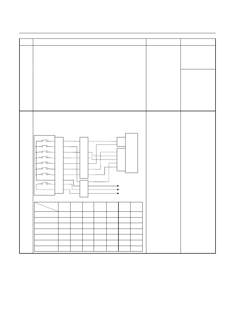
Inspection of inhibitor switch using a Tech 2 or circuit tester.
When the select lever is operated, is the data display in the Tech 2
correct or voltage at each range correct?
Inhibitor SW
TCM
A2 (P)
A17 (3)
B2 (2)
B10 (N)
B11 (D)
B19 (R)
B21 (L)
C95
(2)
(10)
(11)
(19)
(21)
YEL/VIO
RED/BLK
BLU
BLK/GRN
Starter Relay
C94
(2)
(3)
B
H22
(1)
(6)
(4)
(7)
(5)
(2)
P
2
R
N
D
3
L
Start SW
PNK/BLU
E51
(2)
(4)
(8)
(5)
(1)
(9)
(6)
(3)
(10)
(7)
(38)
(15)
(3)
(37)
H4
PNK/BLK
RED/YEL
YEL/VIO
BLK/GRN
PNK/BLK
RED/BLK
BLU
RED/YEL
PNK/BLU
BLK/WHT
BLK
BLK
BLK/WHT
Key Switch
WHT
WHT
Immobiliser Control Unit
TCM terminal
Range
A2
B19
B10
B11
B17
B2
B21
P
Battery
voltage
-
-
-
-
-
-
R
-
Battery
voltage
-
-
-
-
-
N
-
-
Battery
voltage
-
-
-
-
D
-
-
-
Battery
voltage
-
-
-
3
-
-
-
-
Battery
voltage
-
-
2
-
-
-
-
-
Battery
voltage
-
L
-
-
-
-
-
-
Battery
voltage
Go to Step 6
Adjust the inhibitor
switch.
Нет комментариевНе стесняйтесь поделиться с нами вашим ценным мнением.
Текст