Isuzu D-Max / Isuzu Rodeo (TFR/TFS). Manual — part 1871

7A2-100 DIAGNOSIS
Step
Action
Yes
No
6
Inspect the output voltage and throttle opening signal of the throttle
position sensor using a Tech 2 or circuit tester.
Is a voltage value in proportion to the throttle opening output?
TPS
TCM
A16
C56
(28)
C94
(16)
RED/WHT
C56
(49)
(38)
(57)
(69)
ECM
A47 (GND)
A35 (Output)
A26
A55 (+5V)
A69 (Idle SW)
Go to Step 7
Repair the defect or
replace.
7
Check of power supply to and earth of TCM.
Are the power supply and earth proper?
TCM
A1 (+B)
B5
B15
H23
(15)
C95
(5)
(15)
BLK/YEL
BLK
BLK
Battery
C94
(1)
BLK
Go to Step 8
Check the power
source harness and
earth harness (bolt
tightening to the
body).
8
Is the stall revolution correct in D, 3, 2 and L range? Refer the
STALL TEST section in this manual.
Go to Step 6
Repair the defect or
replace.
9
Is the line pressure correct? Refer the LINE PRESSURE TEST
section in this manual.
Trouble in the AT
assembly or control
valve.
Repair the defect or
replace.
DIAGNOSIS 7A2-101
No. B3: Engine Race Up During Starting (Slip)
Description:
•
The engine speeds up but vehicle speed does not increase when the accelerator pedal is stepped on at the
starting.
Diagnosis Hints:
•
Possibility of slip of clutch is supposed. If slip of clutch has occurred, a DTC of "Gear ratio error" is stored.
Possible Cause:
•
Slip
of
clutch.
If slip of clutch is caused, a DTC (gear ratio error) is stored.
•
Dropped line pressure.
•
Trouble in control valve body (faulty operation, sticking, clogged oil passage).
7A2-102 DIAGNOSIS
Step
Action
Yes
No
1
Gear ratio trouble diagnosis.
Travel in the following sequence for about 7 seconds or more in
each range: Start in the L range (1st) to 2 range (2nd) to 3 range
(3rd) to D range (4th) (to detect the gear ratio trouble exactly, this
process should be carried out)
Go to Step 2
Go to Step 2
2
Are any DTCs stored?
Go to DTC Chart
Go to Step 3
3
Are the quantity, contamination and smell normal?
If the ATF level is
low, replenish up to
the specified level.
Go to Step 4
If ATF is extremely
black and
contaminated and
smells burnt, slip of
the clutch is
supposed.
Overhaul the AT
unit.
4
Are the engine speed and other engine system correct?
Go to Step 5
Repair the defect or
replace.
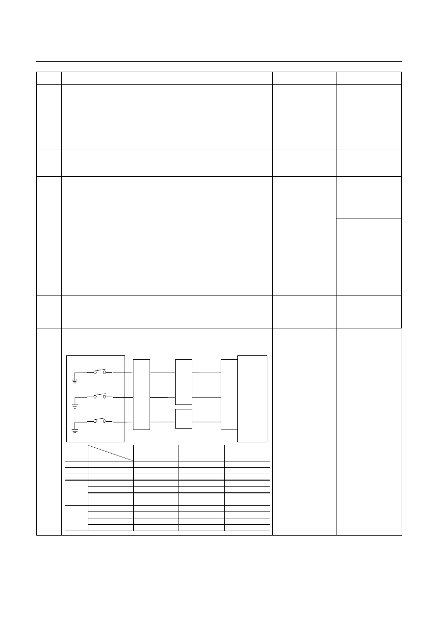
5
Inspection of electrical or mechanical fault
Is the signal from each pressure switch changed synchronously?
Control Valve
TCM
B1
B12
B20
RED/YEL
WHT/BLK
2-4 Brake Pressure SW
Terminal
Assembly
YEL
E54
(7)
(12)
(1)
H23
(12)
(10)
C95
(1)
(12)
(20)
RED/YEL
YEL
WHT/BLK
L&R Brake Pressure SW
High Clutch Pressure SW
H22
(8)
Range
TCM terminal
Gear
B20
(High clutch
pressure SW)
B1
(2-4 brake pressure
SW)
B12 (Low & reverse
brake pressure SW)
P
-
More than 10V
More than 10V
More than 10V
R
Reverse
More than 10V
More than 10V
-
N
-
More than 10V
More than 10V
More than 10V
D, 3, 2
1st
More than 10V
More than 10V
More than 10V
2nd
More than 10V
-
More than 10V
3rd
-
More than 10V
More than 10V
4th
-
-
More than 10V
L
1st
More than 10V
More than 10V
-
2nd
More than 10V
-
More than 10V
3rd
-
More than 10V
More than 10V
4th
-
-
More than 10V
Go to Step 6
Repair the defect or
replace.
DIAGNOSIS 7A2-103
Step
Action
Yes
No
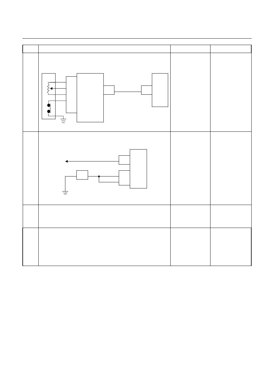
6
Inspect the output voltage and throttle opening signal of the
throttle position sensor using a Tech 2 or circuit tester.
Is a voltage value in proportion to the throttle opening output?
TPS
TCM
A16
C56
(28)
C94
(16)
RED/WHT
C56
(49)
(38)
(57)
(69)
ECM
A47 (GND)
A35 (Output)
A26
A55 (+5V)
A69 (Idle SW)
Go to Step 7
Repair the defect or
replace.
7
Check of power supply to and earth of TCM.
Are the power supply and earth proper?
TCM
A1 (+B)
B5
B15
H23
(15)
C95
(5)
(15)
BLK/YEL
BLK
BLK
Battery
C94
(1)
BLK
Go to Step 8
Check the power
source harness and
earth harness (bolt
tightening to the
body).
8
Is the stall revolution correct in D, 3, 2 and L range? Refer the
STALL TEST section in this manual.
Go to Step 9
Repair the defect or
replace.
9
Is the line pressure correct? Refer the LINE PRESSURE TEST
section in this manual.
Trouble in the AT
assembly or control
valve.
Repair the defect or
replace.
Нет комментариевНе стесняйтесь поделиться с нами вашим ценным мнением.
Текст