Isuzu D-Max / Isuzu Rodeo (TFR/TFS). Manual — part 577
6A – 146 ENGINE MECHANICAL
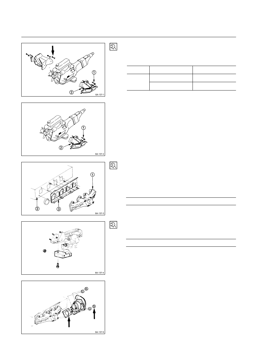
5. Engine
Mounting
Bracket
Install the engine mounting bracket to the cylinder body
and tighten the bracket bolts to the specified torque.
Mounting Bracket Bolt Torque
kg·m (lb.ft/N·m)
Right Side M10
× 1.25 (9T)
5.6 (40.5/54.9)
M10
× 1.25 (7T)
4.1 (30/40)
Left Side
M14
× 1.50 (7T)
12 (86.7/118)
6. Exhaust
Manifold
1) Install the exhaust manifold
to the cylinder head
with the manifold gasket
.
2) Tighten the exhaust manifold bolts to the specified
torque a little at a time.
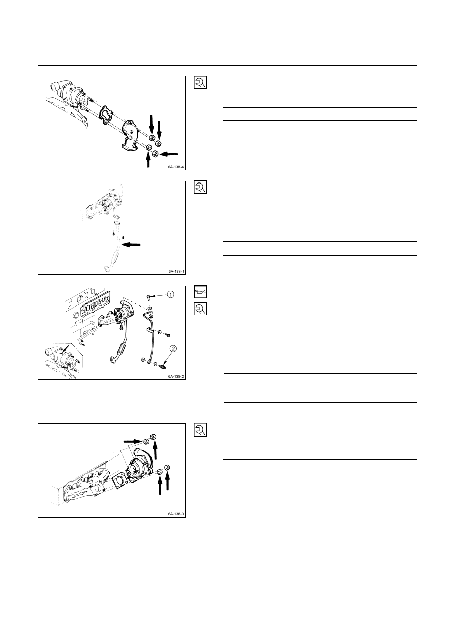
Exhaust Manifold Bolt Torque
kg·m (lb.ft/N·m)
2.7
± 0.5 (19.5 ± 3.6/26.5 ± 4.9)
3) Install the exhaust manifold bracket to the manifold
and the cylinder body.
Manifold Bracket Bolt Torque
kg·m (lb.ft/N·m)
1.9
± 0.5 (13.7 ± 3.6/18.6 ± 4.9)
8. Turbocharger
1) Install the turbocharger and the gasket.
2) Temporarily tighten the turbocharger nuts at this time.
They will be fully tightened after the installation of the
turbocharger oil pipe.
Always install new nuts and new gasket.
ENGINE MECHANICAL 6A – 147
3) Install the exhaust adapter with gasket and tighten the
adapter nut to the specified torque.
Adapter Nut Torque
kg·m (lb.ft/N·m)
2.7
± 0.5 (19.5 ± 3.6/26.5 ± 4.9)
9. Turbocharger Oil Return Pipe
1) Install the oil return pipe with gasket to the
turbocharger.
2) Tighten the turbocharger oil return pipe to the
specified torque.
Turbocharger Oil Reutrn Pipe Torque
kg·m (lb.ft/N·m)
0.8
± 0.2 (5.8 ± 1.4/7.8 ± 2.0)
10. Turbocharger Oil Feed Pipe
1) Before installing the oil feed pipe, supply 10 – 20 cc of
clean engine oil to the turbocharger center housing
through the oil feed opening.
2) Turn the rotating assembly with your hand to
thoroughly lubricate the internal parts.
3) Tighten the oil feed pipe to the specified torque.
Turbocharger Oil Feed Pipe Joint
Bolt Torque
kg·m (lb.ft/N·m)
M10
× 1.5 2.25 ± 0.25 (16.3 ± 1.8/22.1 ± 2.5)
M14
× 1.5 5.5 ± 0.25 (39.8 ± 1.8/53.9 ± 2.5)
4) Tighten the turbocharger nut to the specified torque.
Turbocharger Nut Torque
kg·m (lb.ft/N·m)
2.7
± 0.5 (19.5 ± 3.6/26.5 ± 4.9)
6A – 148 ENGINE MECHANICAL
v
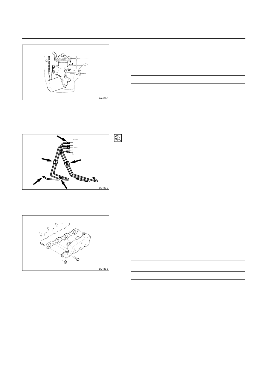
11. Oil Cooler with Oil Filter
1) Install the O-ring to the oil filter flange groove.
2) Tighten the oil filter and oil cooler to the specified
torque.
Oil Filter Flange Bolt Torque
kg·m (lb.ft/N·m)
1.9
± 0.5 (13.7 ± 3.6/18.6 ± 4.9)
3) Lightly oil the O-ring of oil filter cartridge.
4) Turn in the new oil filter cartridge by hand until the
sealing face is fitted again the O-ring.
5) Use the filter wrench to turn in the oil filter and
additional one and 1·1/8 turns.
6) Start the engine and check for oil leakage from oil
filter.
14. Fuel Injection Pipe with Clip
1) Temporarily tighten the injection pipe sleeve nut.
2) Set the clip in the illustrated position.
Note:
Make absolutely sure that the clip is correctly
positioned.
An improperly positioned clip will result in injection
pipe breakage and fuel pulsing noise.
3) Tighten the injection pipe sleeve nut to the specified
torque.
Injection Pipe Sleeve Nut Torque
kg·m (lb.ft/N·m)
3
± 1 (21.7 ± 7.2/29.4 ± 9.8)
16. Intake Manifold
1) Install the manifold gasket to the intake manifold.
2) Connect the intake rubber hose to the intake duct.
3) Tighten the intake manifold bolts and the flange nuts
to the specified torque.
Intake Manifold Bolt Torque
kg·m (lb.ft/N·m)
1.9
± 0.5 (13.7 ± 3.6/18.6 ± 4.9)
Intake Manifold Flange Nut Torque
kg·m (lb.ft/N·m)
1.9
± 0.5 (13.7 ± 3.6/18.6 ± 4.9)
4) Connect the PCV hose to the cylinder head cover.
ENGINE MECHANICAL 6A – 149
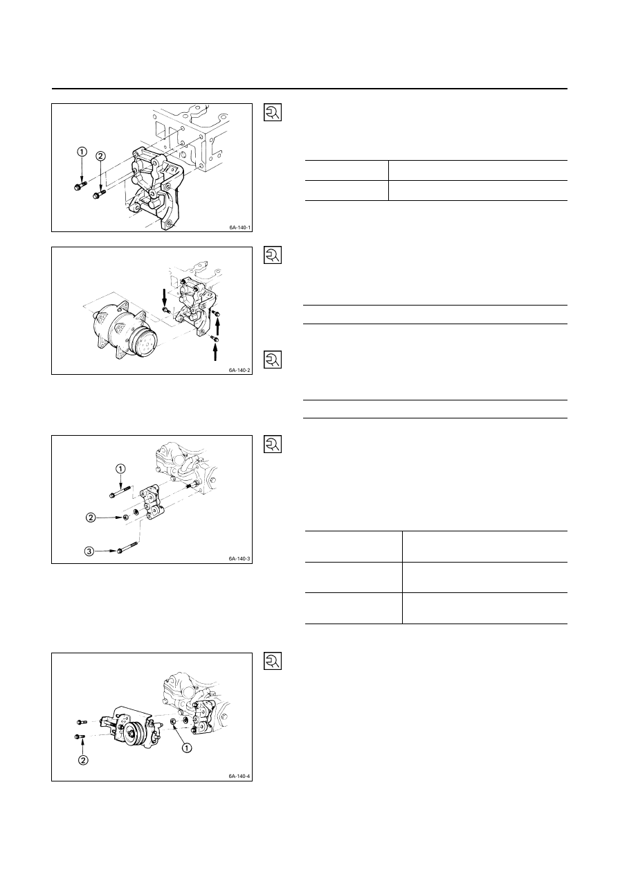
17. Compressor Bracket
1) Install the compressor bracket to the cylinder head.
2) Tighten the bracket bolts to the specified torque.
Bracket Bolt Torque
kg·m (lb.ft/N·m)
M 8
× 1.25
1.9
± 0.5 (13.7 ± 3.6/18.6 ± 4.9)
M10
× 1.25
4.1
± 0.6 (30 ± 7.2/40 ± 6)
18. Compressor
1) Install the compressor to the compressor bracket.
2) Tighten the compressor bolts to the specified torque.
Compressor Bolt Torque
kg·m (lb.ft/N·m)
3.8
± 1.0 (27.5 ± 7.2/37.2 ± 9.8)
19. Starter Motor
Tighten the starter motor bolts to the specified torque.
Starter Motor Bolt Torque
kg·m (lb.ft/N·m)
7.0
± 1.0 (50.6 ± 7.2/68.6 ± 9.8)
20. Power Steering Oil Pump Bracket
21. Power Steering Oil Pump
1) Install the oil pump bracket to the cylinder head.
2) Tighten the pump bracket nut and bolts to the
specified torque.
Oil Pump Bracket Nut and Bolt
Torque kg·m
(lb.ft/N·m)
M10
× 1.25 (7T)
3.75
± 0.95
(27.1
± 6.9/36.75 ± 9.31)
M 8
× 1.25 (7T)
1.75
± 0.55
(12.7
± 4.0/17.75 ± 5.39)
M 8
× 1.25 (4T)
1.30
± 0.50
(9.4
± 3.6/12.74 ± 4.90)
3) Install the oil pump to the bracket.
4) Temporarily tighten the oil pump nut
and bolts
.
The nut and bolts will be finally tightened after
installation of the drive belt.
Нет комментариевНе стесняйтесь поделиться с нами вашим ценным мнением.
Текст