Isuzu D-Max / Isuzu Rodeo (TFR/TFS). Manual — part 576
6A – 142 ENGINE MECHANICAL
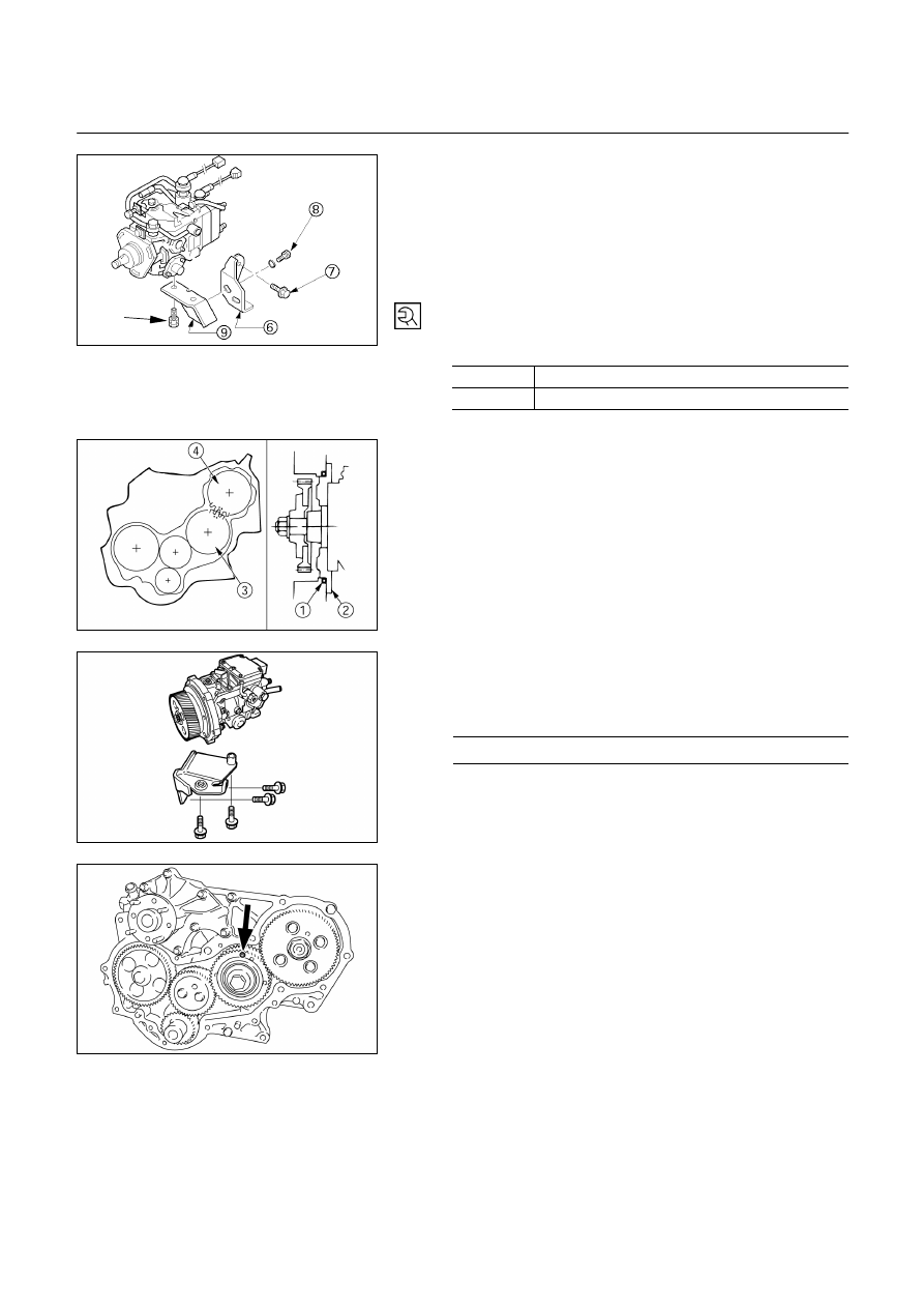
3) Install the injection pump rear bracket
and the rear
bracket bolts
to the cylinder body.
4) Install the rear bracket bolts
to the injection pump
bracket
.
5) Tighten the injection pump bracket bolts to the
specified torque.
Injection Pump Bracket Bolt Torque
kg·m (lb.ft/N·m)
,
1.9
± 0.5 (13.7 ± 3.6/18.6 ± 4.9)
4.1
± 0.6 (29.6 ± 4.3/40.2 ± 5.9)
4JA1TC, 4JH1TC
1) Install
the
O-ring
to the injection pump flange
.
2) Install the injection pump to the timing gear case.
Align the idler gear “B”
“‥” mark with the injection
pump timing gear
“‥” mark.
3) Install the injection pump bracket.
4) Tighten the injection pump bracket bolts to the
specified torque.
Injection Pump Bracket Bolt Torque
kg·m (lb.ft/N·m)
4.1
± 0.6 (29.6 ± 4.3/40.2 ± 5.9)
5) Remove the scissor gear set bolt.
020L200021
080L200006
ENGINE MECHANICAL 6A – 143
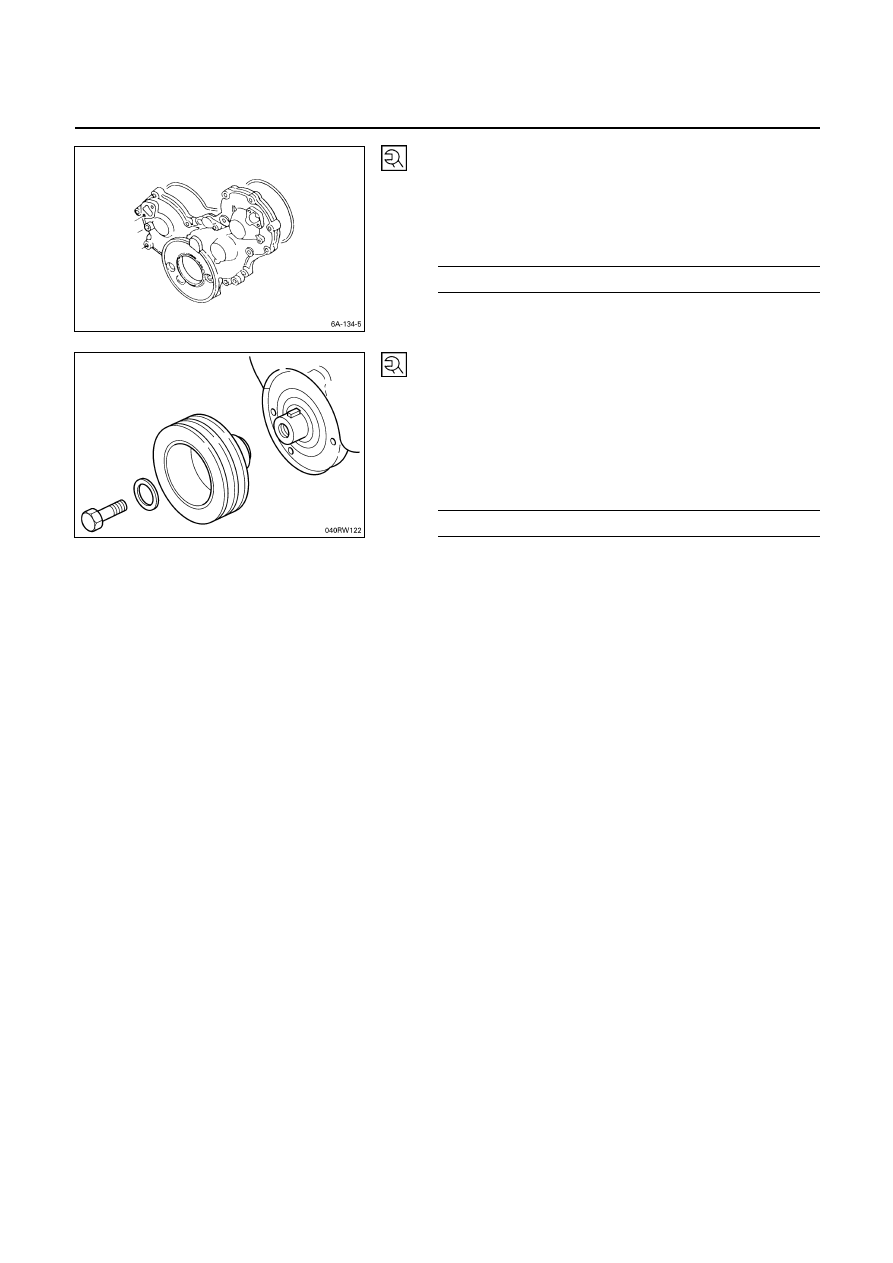
10. Timing Gear Case Cover
6) Align the gear case with the timing gear case knock
pin and then install the timing gear case cover.
7) Tighten the gear case cover bolts to the specified
torque.
Gear Case cover Bolt Torque
kg·m (lb.ft/N·m)
1.9
± 0.5 (13.7 ± 3.6/18.6 ± 4.9)
13. Crankshaft Damper Pulley
Tighten the crankshaft damper pulley bolt to the specified
torque.
Note:
Hold the flywheel ring gear stationary to prevent the
crankshaft from turning when tightening the damper
pulley.
Crankshaft Damper Pulley Bolt Torque
kg·m (lb.ft/N·m)
21.0
± 2.0 (151.9 ± 14.5/206.0 ± 19.6)
Take care not to damage the crankshaft damper pulley
boss.
6A – 144 ENGINE MECHANICAL
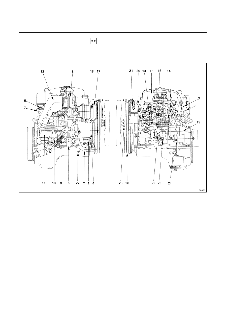
INSTALLATION
EXTERNAL PARTS
These installation steps are based on the 4JB1T engine.
Installation Steps
J
1.
Generator bracket
J
16. Intake manifold
J
2.
Water inlet pipe
J
17. Compressor bracket
J
3. Heater pipe (Rear side)
J
18. Compressor
J
4. Generator and adjusting plate
J
19. Starter motor
J
5.
Engine mounting bracket
J
20. Power steering oil pump bracket
J
6.
Exhaust manifold
J
21. Power steering oil pump
7.
Exhaust manifold heat protector
22.
Water drain cock
J
8. Turbocharger
23.
Oil pressure warning switch and
J
9. Turbocharger oil return pipe
nipple
J
10. Turbocharger oil feed pipe
24.
Oil level gauge guide tube
J
11. Oil cooler with Oil filter
J
25. Cooling fan pulley
12.
Turbocharger heat protector
J
26. Cooling fan drive belt
13.
Injection
pump
27.
Vacuum
pipe
J
14. Fuel injection pipe with clip
15.
Fuel leak off pipe
ENGINE MECHANICAL 6A – 145
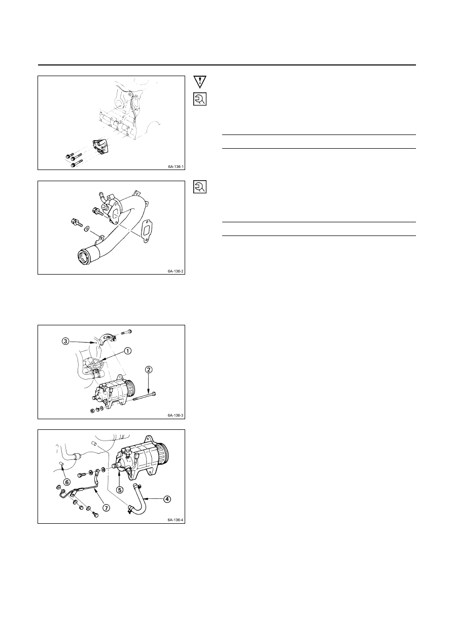
Important Operations
1. Generator
Bracket
Install the generator bracket to the cylinder body and
tighten the bracket bolts to the specified torque.
Bracket Bolt Torque
kg·m (lb.ft/N·m)
4.1
± 0.6 (29.7 ± 4.3/40.2 ± 5.9)
2. Water
Inlet
Pipe
1) Tighten the water inlet pipe bolts to the specified
torque.
Suction Pipe Bolt Torque
kg·m (lb.ft/N·m)
1.9
± 0.5 (13.7 ± 3.6/18.6 ± 4.9)
3. Heater Pipe (Rear Side)
1) Install the heater pipe to the cylinder head.
2) Connect the oil cooler return hose and feed hose to
the oil cooler.
3) Connect the water rubber hose to the heater pipe.
4. Generator and Adjusting Plate
1) Install the generator to the bracket
.
2) Temporarily tighten the generator bolt
and
adjusting plate bolts
.
The bolts will be finally tightened after installation of
the cooling fan drive belt.
3) Connect the vacuum pump rubber hose
to the
vacuum pump
, and the oil pan
.
4) Connect the vacuum oil pipe
to the vacuum pump,
and the cylinder body.
Нет комментариевНе стесняйтесь поделиться с нами вашим ценным мнением.
Текст