Isuzu D-Max / Isuzu Rodeo (TFR/TFS). Manual — part 995
BRAKES 5-51
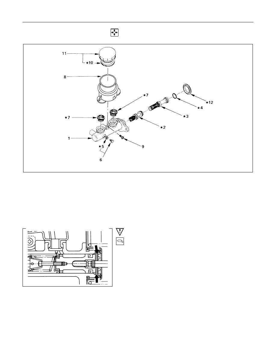
REASSEMBLY
★
; Repair Kit
Reassembly Steps
▲
1. Cylinder assembly ; brake, master
▲
2. Piston assembly ; secondary and spring
▲
3. Piston assembly ; primary and spring
4. Ring ; snap
5. Gasket
▲
6. Bolt ; stopper
▲
7. Grommet
8. Reservoir ; fluid, brake
▲
9. Screw
10. Seal
11. Cover ; fluid reservoir
▲
12. Dust seal
Important Operations
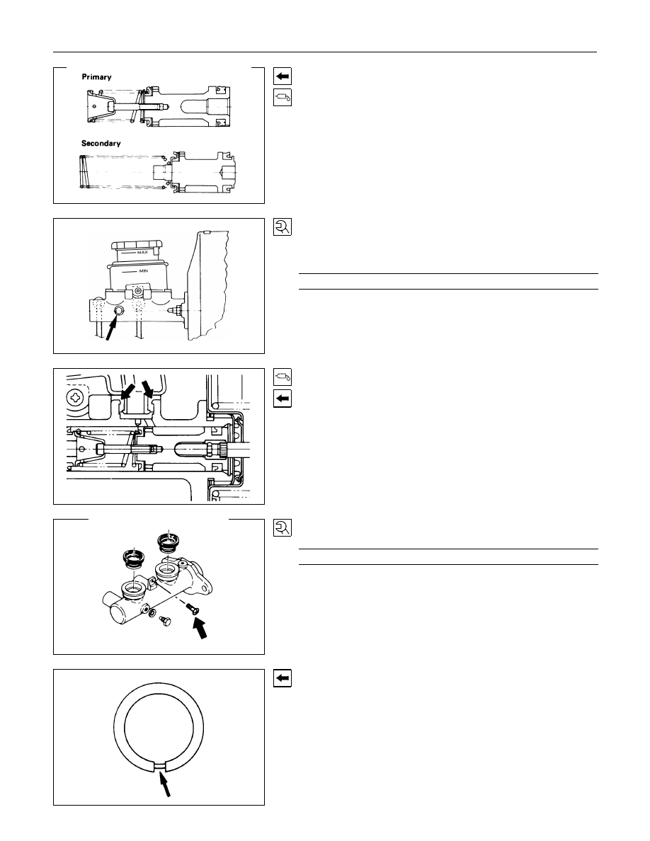
1. Cylinder Assembly ; Brake, Master
Lubricate the master cylinder bore with clean rubber
grease.(arrowed portion)
5-52 BRAKES
2. Piston Assembly ; Secondary and Spring
3. Piston Assembly ; Primary and Spring
Lubricate the piston cups on the primary piston assemblies with
rubber grease.
Take care not to scratch the piston cup when installing the
piston assemblies.
Note:
Don't remove the spring from the piston.
6. Bolt ; Stopper
Depress the primary piston and install the piston stopper bolt
with a new gasket.
Torque
N
⋅
m(kgf
⋅
m/lb
⋅
ft)
6.9 - 8.8 (0.7 - 0.9 / 5.1 - 6.5)
7. Grommet
Lubricate the new grommets with clean rubber grease.
Insert the grommets, with the flared side up, into the cylinder
body.
Apply rubber grease to the dust seal portion.
(The portion indicated by the arrows in the left diagram.)
9. Screw
Torque
N
⋅
m(kgf
⋅
m/lb
⋅
ft)
1.0 - 2.0 (0.01 - 0.20 / 0.7 - 1.5)
12.Dust Seal
Install the dust seal so that its groove faces downward.
BRAKES 5-53
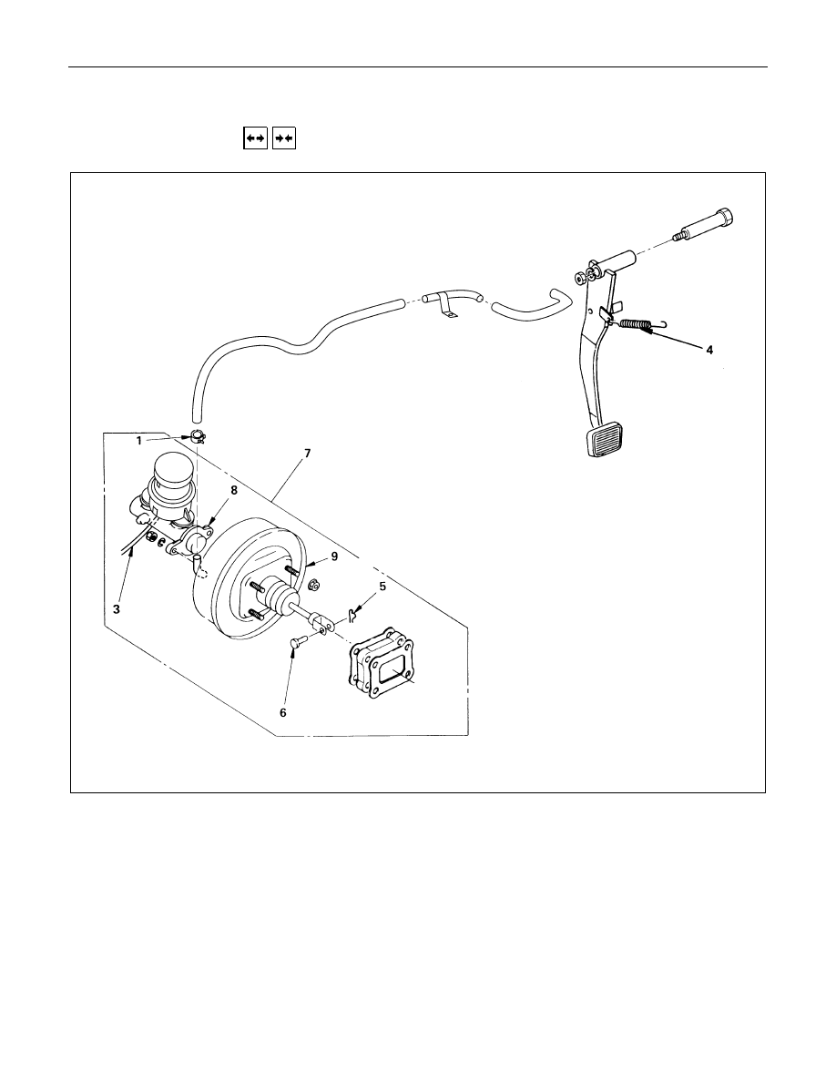
VACUUM SERVO
REMOVAL AND INSTALLATION
Removal Steps
1. Clamp ; vacuum hose
2. Vacuum hose
▲
3. Brake line
4. Return spring ; brake pedal
5. Snap pin
6. Pin ; push rod to brake pedal
7. Vacuum servo to dash panel and pedal
mounting bracket
8. Maser cylinder assembly
9. Vacuum servo assembly
Installation Steps
9. Vacuum servo assembly
▲
8. Maser cylinder assembly
▲
7. Vacuum servo to dash panel and pedal
mounting bracket
6. Pin ; push rod to brake pedal
5. Snap pin
4. Return spring ; brake pedal
▲
3. Brake line
▲
2. Vacuum hose
1. Clamp ; vacuum hose
5-54 BRAKES
Important Operation - Removal
3. Brake Line
When handling, be careful not to spill brake fluid over the
painted surfaces, as damage to the paint finish will result.
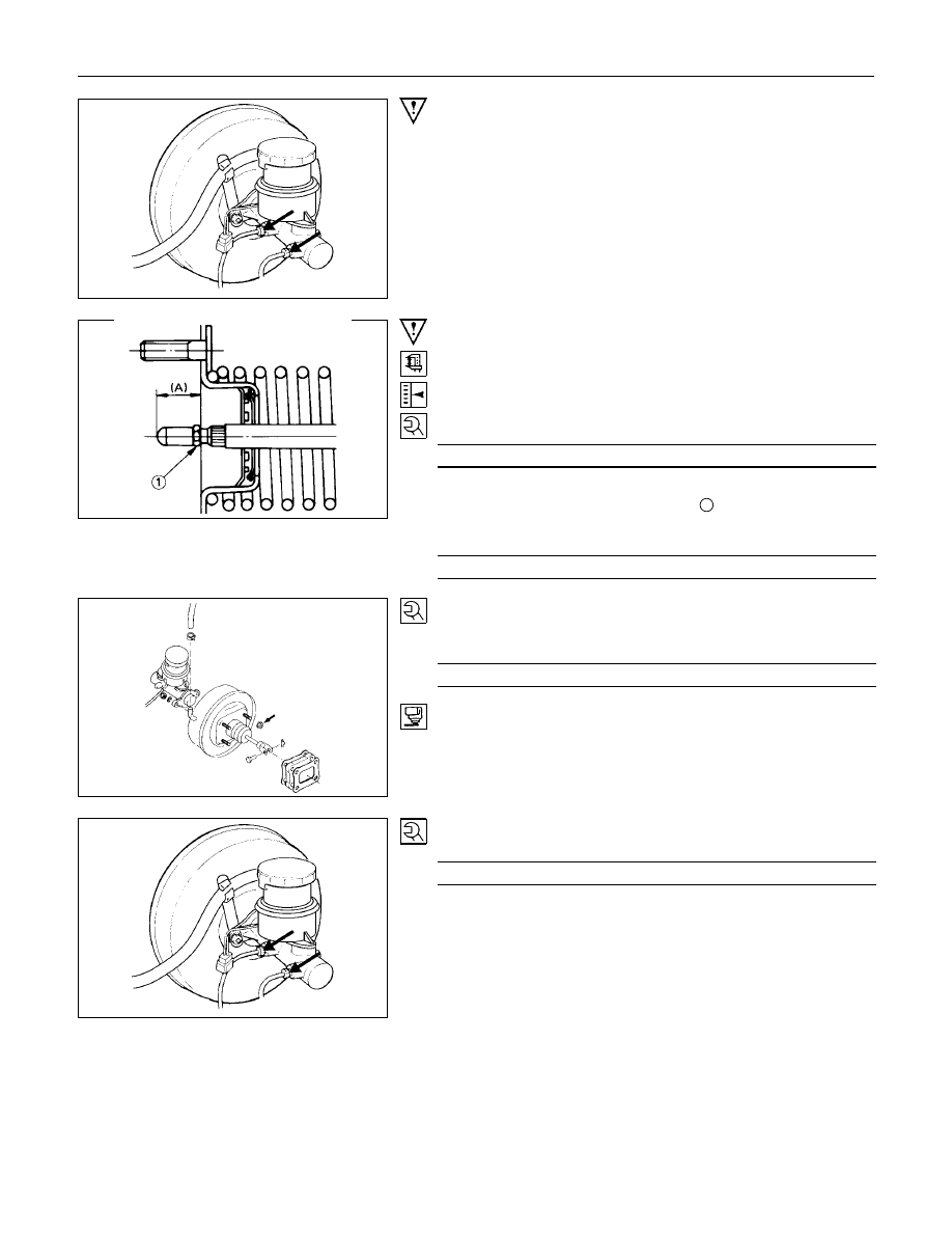
Important Operation - Installation
8. Master Cylinder Assembly
Check the distance from the flange face of the vacuum servo
to the end of the push rod before installation of the master
cylinder.
Projection (A)
mm(in)
18.0 - 18.2 (0.709 - 0.717)
If the measured distance deviates from the specified range,
make an adjustment with the lock nut
1
at the end of the push
rod.
Torque
N
⋅
m(kgf
⋅
m/lb
⋅
ft)
15 - 25 (1.5 - 2.5 / 11 - 18)
7. Vacuum Servo to Dash Panel and Pedal Mounting
Bracket
Torque
N
⋅
m(kgf
⋅
m/lb
⋅
ft)
22 - 31 (2.2 - 3.2 / 16 - 23)
Apply sealer to the dashboard fitting face.
3. Brake Line
Torque
N
⋅
m(kgf
⋅
m/lb
⋅
ft)
9 - 15 (0.9 - 1.5 / 6.5 - 11)
Нет комментариевНе стесняйтесь поделиться с нами вашим ценным мнением.
Текст