Isuzu D-Max / Isuzu Rodeo (TFR/TFS). Manual — part 993
BRAKES 5-43
Important Operations
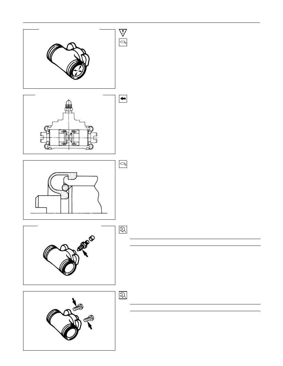
1. Bode ; Wheel Cylinder
Lubricate the cylinder bore with clean rubber grease.
4. Piston Assembly
Install new piston cups on each piston so that the flared end of
the cups are turned to the inboard side of the pistons.
Attach the return spring and the boot to the piston.
Apply DELCO silicone lube No.5459912 (or equivalent) to the
piston and the inner face of the boots.
6. Bleeder ; Wheel Cylinder
Torque
N
⋅
m(kgf
⋅
m/Ib
⋅
ft)
6.9 - 11.8 (0.7 - 1.2 / 5.1 - 8.7)
7. Wheel Cylinder Assembly
Torque
N
⋅
m(kgf
⋅
m/Ib
⋅
ft)
11 - 15 (1.1 - 1.5 / 8 - 11)
5-44 BRAKES
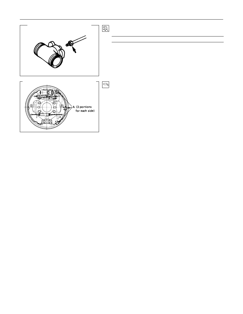
18.Brake Line
Torque
N
⋅
m(kgf
⋅
m/Ib
⋅
ft)
13 - 19 (1.3 - 1.9 / 9 - 14)
Apply grease lightly to back plate A.
BRAKES 5-45
BRAKE CONTROL
REMOVAL AND INSTALLATION
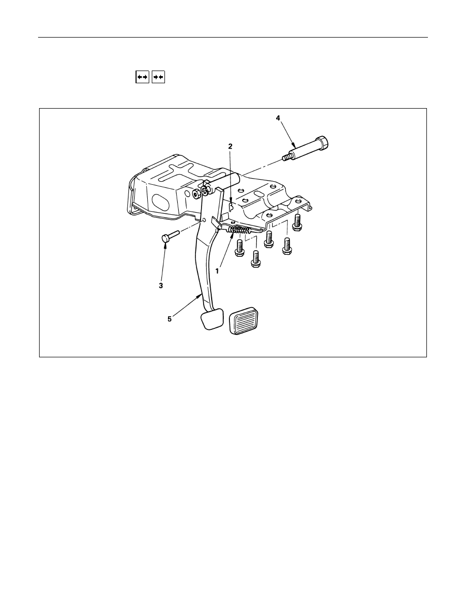
BRAKE PEDAL ASSEMBLY
This illustration based on the LHD model
Removal Steps
1. Return spring
2. Snap pin
3. Pin ; push rod to pedal
4. Pin ; fulcrum, pedal to bracket
5. Pedal assembly with bush
Installation steps
To install, follow the removal procedure in
reverse order.
Before installation, appyl grease to the entire
circumference of the fulcrum pin (4) and push
rod pin (3).
Refer to "SERVICING" in this section for
adjustment procedure of brake pedal.
5-46 BRAKES
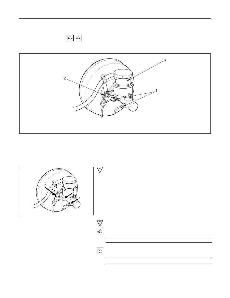
MASTER CYLINDER
REMOVAL AND INSTALLATION
BRAKE PEDAL ASSEMBLY
This illustration based on the LHD model.
Removal Steps
▲
1. Brake line
2. Nut ; master cylinder to vacuum servo
3. Master cylinder assembly
Installation Steps
3. Master cylinder assembly
▲
2. Nut ; master cylinder to vacuum servo
▲
1. Brake line
Important Operation - Removal
1. Brake Line
Be very careful not to spill brake fluid on the painted surface.
Damage to the painted surface will result.
Important Operation - Installation
2. Nut ; Master Cylinder to Vacuum Servo
Torque
N
⋅
m (kgf
⋅
m/lb
⋅
ft)
1.0 - 1.6 (7 - 12 / 9.8 - 16)
1. Brake Line
Torque
N
⋅
m (kgf
⋅
m/lb
⋅
ft)
0.9 - 1.5 (6.5 - 11 / 8.8 - 15)
Нет комментариевНе стесняйтесь поделиться с нами вашим ценным мнением.
Текст