Isuzu D-Max / Isuzu Rodeo (TFR/TFS). Manual — part 56
4JA1-TC/4JH1-TC ENGINE DRIVEABILITY AND EMISSIONS
6E–219
5
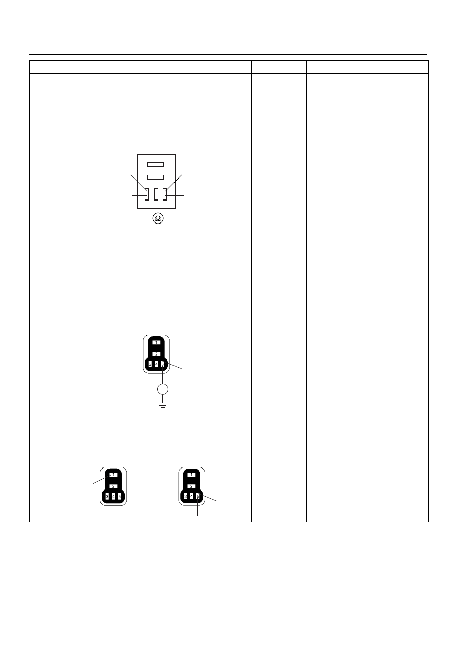
Using the DVM and check the A/C compressor relay.
1. Ignition “Off”, engine “Off”.
2. Remove the A/C compressor relay from the relay
box.
3. Check the relay coil.
Was the DVM indicated specified value?
Continuity
Go to Step 6
Replace A/C
compressor
relay and verify
repair
6
Using the DVM and check the A/C compressor relay
power supply circuit.
1. Ignition “On”, engine “Off”.
2. Remove the A/C compressor relay from the relay
box.
3. Check the circuit for open or short to ground
circuit.
Was the DVM indicated specified value?
Battery
voltage
Go to Step 8
Go to Step 7
7
Repair the open or short to ground circuit between the
ECM main relay and A/C compressor relay.
Is the action complete?
—
Verify repair
—
Step
Action
Value(s)
Yes
No
5
3
A/C Compressor Relay
5
V
X-5
4JA1-TC
X-10
4JH1-TC
5
1
X-5
4JA1-TC
X-10
4JH1-TC
X-4

6E–220
4JA1-TC/4JH1-TC ENGINE DRIVEABILITY AND EMISSIONS
8
Using the DVM and check the A/C compressor relay
ground circuit.
Breaker box is available:
1. Ignition “Off”, engine “Off”.
2. Install the breaker box as type A. (ECM
disconnected)
3. Remove the A/C compressor relay from the relay
box.
4. Check the circuit for open or short to ground
circuit.
Was the problem found?
Breaker box is not available:
1. Ignition “Off”, engine “Off”.
2. Disconnect the ECM connector.
3. Remove the A/C compressor relay from the relay
box.
4. Check the circuit for open or short to ground
circuit.
Was the problem found?
—
Repair faulty
harness and
verify repair
Go to Step 9
9
Is the ECM programmed with the latest software
release?
If not, download the latest software to the ECM using
the “SPS (Service Programming System)”.
Was the problem solved?
—
Verify repair
Go to Step 10
Step
Action
Value(s)
Yes
No
41
3
X-5
4JA1-TC
X-10
4JH1-TC
41
3
C-56
X-5
4JA1-TC
X-10
4JH1-TC

4JA1-TC/4JH1-TC ENGINE DRIVEABILITY AND EMISSIONS
6E–221
10
Replace the ECM.
Is the action complete?
IMPORTANT: The replacement ECM must be
programmed. Refer to section of the Service
Programming System (SPS) in this manual.
Following ECM programming, the immobiliser system
(if equipped) must be linked to the ECM. Refer to
section 11 “Immobiliser System-ECM replacement” for
the ECM/Immobiliser linking procedure.
—
Verify repair
—
Step
Action
Value(s)
Yes
No

6E–222
4JA1-TC/4JH1-TC ENGINE DRIVEABILITY AND EMISSIONS
Diagnostic Trouble Code (DTC) P0645 (Symptom Code 8) (Flash Code 46) A/C
Compressor Relay Circuit Voltage High
Step
Action
Value(s)
Yes
No
1
Was the “On-Board Diagnostic (OBD) System Check”
performed?
—
Go to Step 2
Go to On Board
Diagnostic
(OBD) System
Check
2
1. Connect the Tech 2.
2. Review and record the failure information.
3. Select “F0: Read DTC Infor As Stored By ECU” in
“F0: Diagnostic Trouble Codes”.
Is the DTC P0645 (Symptom Code 8) stored as
“Present Failure”?
—
Go to Step 3
Refer to
Diagnostic Aids
and Go to Step
3
3
1. Using the Tech 2, ignition “On” and engine “Off”.
2. Select “F1: Clear DTC Information” in “F0:
Diagnostic Trouble Codes” with the Tech 2 and
clear the DTC information.
3. Operate the vehicle and monitor the “F0: Read
DTC Infor As Stored By ECU” in the “F0:
Diagnostic Trouble Codes”.
Was the DTC P0645 (Symptom Code 8) stored in this
ignition cycle?
—
Go to Step 4
Refer to
Diagnostic Aids
4
Is the ECM programmed with the latest software
release?
If not, download the latest software to the ECM using
the “SPS (Service Programming System)”.
Was the problem solved?
—
Verify repair
Go to Step 5
5
Substitute a known good ECM and recheck.
Was the problem solved?
IMPORTANT: The replacement ECM must be
programmed. Refer to section of the Service
Programming System (SPS) in this manual.
Following ECM programming, the immobiliser system
(if equipped) must be linked to the ECM. Refer to
section 11 “Immobiliser System-ECM replacement” for
the ECM/Immobiliser linking procedure.
—
Go to Step 6
—
6
Replace the ECM.
Is the action complete?
IMPORTANT: The replacement ECM must be
programmed. Refer to section of the Service
Programming System (SPS) in this manual.
Following ECM programming, the immobiliser system
(if equipped) must be linked to the ECM. Refer to
section 11 “Immobiliser System-ECM replacement” for
the ECM/Immobiliser linking procedure.
—
Verify repair
—
Нет комментариевНе стесняйтесь поделиться с нами вашим ценным мнением.
Текст