Isuzu D-Max / Isuzu Rodeo (TFR/TFS). Manual — part 1519
8-176 ELECTRICAL-BODY AND CHASSIS
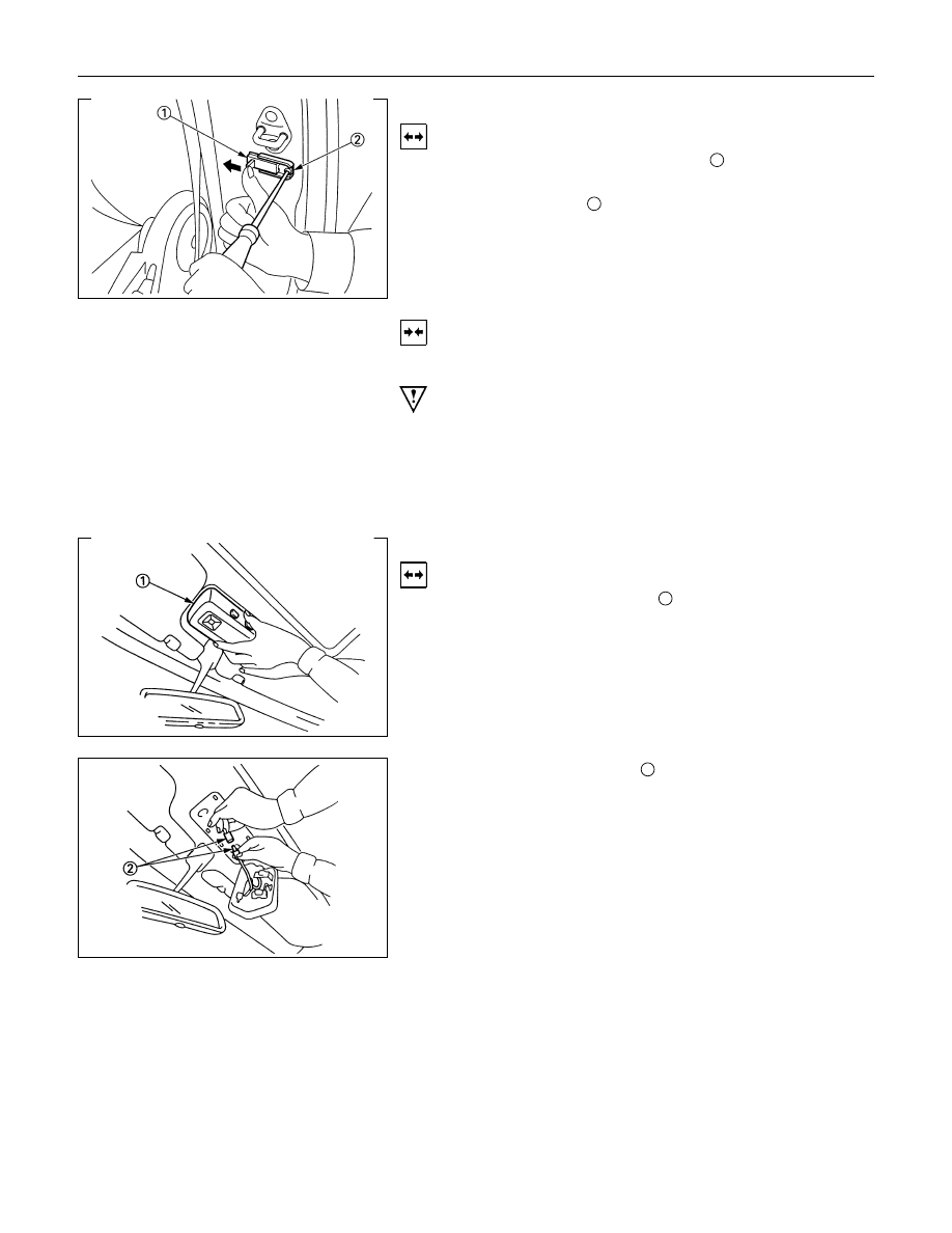
DOOR SWITCH
Removal
1. Push the door switch sliding portion
1
in the direction of the
arrow in the illustration.
2. Loosen the screw
2
.
3. Pull the switch free to remove it.
4. Disconnect the door switch connector.
Installation
Follow the removal procedure in the reverse order to install the
spot light.
Pay close attention to the important points mentioned in the
following paragraphs.
Connector
Be absolutely sure that the door switch connector is securely
connected.
This will prevent a poor contact and an open circuit.
SPOT LIGHT
Removal
1. Grasp the spot light housing
1
with both hands.
Pull the housing straight down.
This will release the clip.
2. Disconnect the connector
2
.
3. Push the bulb in and turn it counterclockwise to remove it.
ELECTRICAL-BODY AND CHASSIS 8-177
Installation
Follow the removal procedure in the reverse order to install the
spot light.
Pay close attention to the important points mentioned in the
following paragraphs.
Connector
Be absolutely sure that the spot light connector is securely
connected.
This will prevent a poor contact and an open circuit.
Bulb
Be absolutely sure that the spot light bulb is correctly installed.
This will prevent a poor contact and an open circuit.
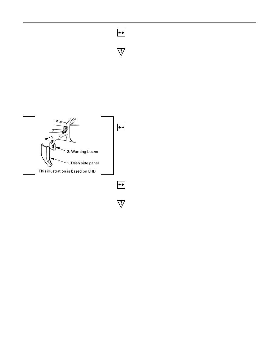
WARNING BUZZER (For Gulf only)
Removal
1. Dash Side Panel
2. Warning Buzzer
• Disconnect the connector.
• Remove the screw.
Installation
Follow the removal procedure in the reverse order to install the
warning buzzer.
Pay close attention to the important points mentioned in the
following paragraphs.
Connector
Be absolutely sure that the warning buzzer connector is
securely connected.
This will prevent a poor contact and an open circuit.
8-178 ELECTRICAL-BODY AND CHASSIS
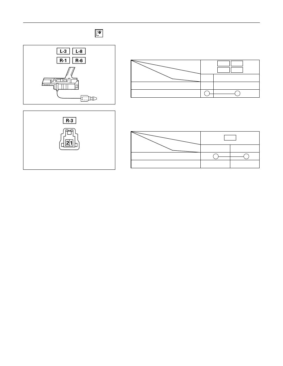
INSPECTION AND REPAIR
DOOR SWITCH
Door Switch Connections
Connector
SW
No.
L-3
L-8
R-1
R-6
position
Terminal No.
1Body Ground
PUSHED
RELEASED
Switch side
SEAT BELT SWITCH (GULF, SOUTH
AFRICA)
Seat Belt Switch Connections
Connector
SW
No.
R-3
position
Terminal No.
1
2
ON (Belt tongue removed)
OFF (Belt tongue inserted)
ELECTRICAL-BODY AND CHASSIS 8-179
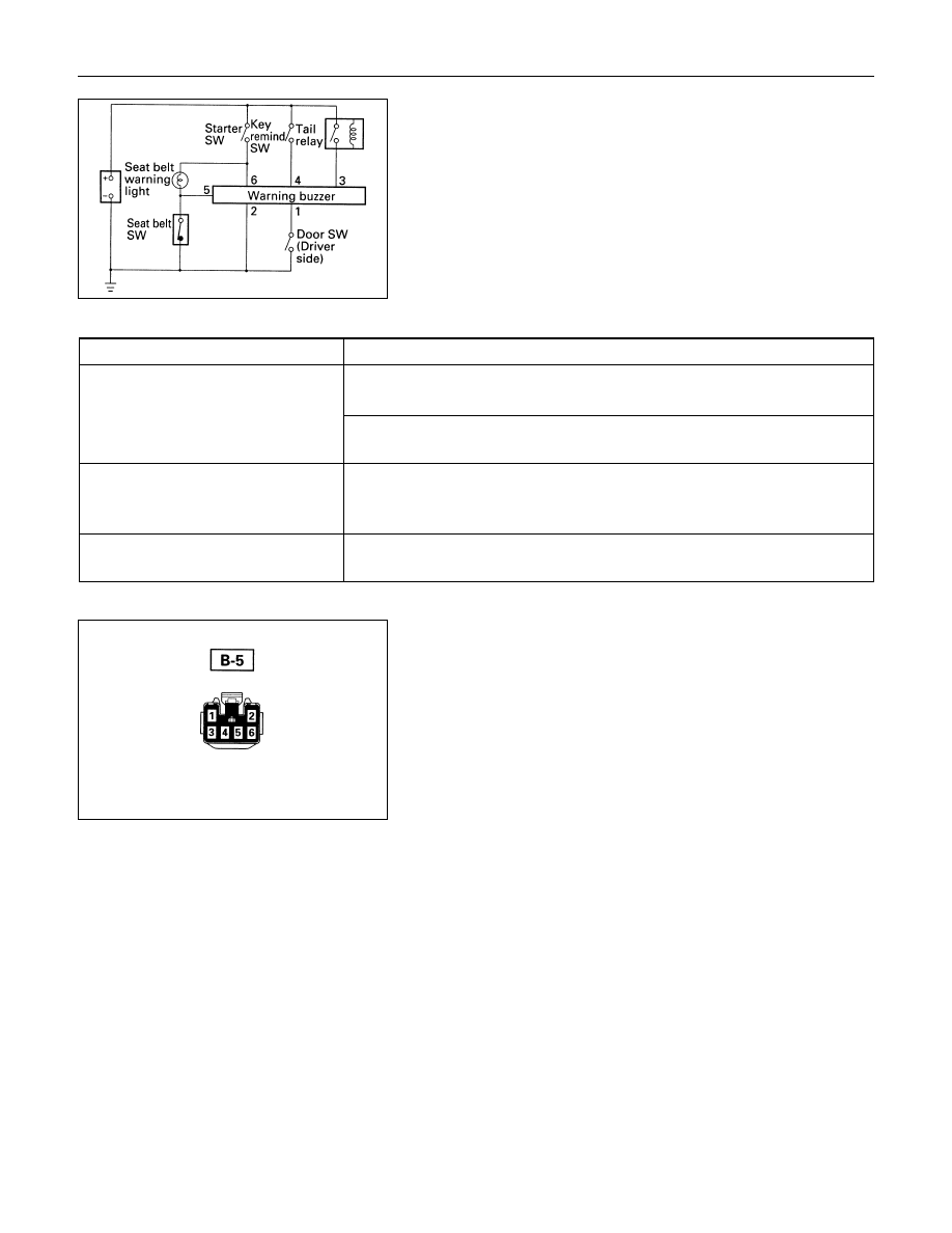
WARNING BUZZER
1. Warning Buzzer Circuit
Warning function
Operational conditions
The warning light meter assembly turned about 6 seconds from the
moment the starter switch is turned on.
The buzzer sounds for about 6 seconds when the starter switch is turned
on with the seat belt switch on (when the seat belt is not used).
Key left in starter switch
The buzzer sounds when both the key remind switch and the FRT door
switch-LH are turned on.
To stop the sound of the buzzer, turn on the starter switch.
Tail lights left on
The buzzer sounds when the starter switch is turned from the “on” to “off”
position while the taillights are on.
Harness side
2. Warning Buzzer Harness Side Connector Circuit
Disconnect the warning buzzer connector and check
continuity and voltage between the warning buzzer harness
side connector terminals.
Fasten the seat belt
Нет комментариевНе стесняйтесь поделиться с нами вашим ценным мнением.
Текст