Isuzu D-Max / Isuzu Rodeo (TFR/TFS). Manual — part 1518
8-172 ELECTRICAL-BODY AND CHASSIS
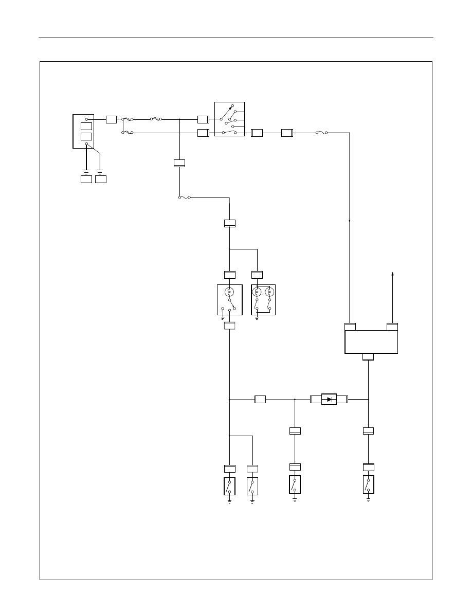
CIRCUIT DIAGRAM (EC-LHD)
H - 9
R - 1
L- 8
P - 1
P - 5
P - 6
8 B
BODY
+
_
P - 10
30B/Y
ENG.
8B/R
P - 2
C - 41
C - 41
ACC
STARTER SW
IG2
ST
IG1
MAIN
80A
1
3
OFF
3 W
C - 41
6
B2
B1
CB-7
15A METER
1
RR DOOR SW-RH
1
RR DOOR SW-LH
L - 1
1
1
OFF
ON
DOOR
DOME LIGHT
H - 11
2
0.85 R/W
H - 11
1
L-2
L - 9
1
MAP LIGHT
0.85 B/W
1
FRT DOOR SW-PASSENGER SIDE
B - 30
3
B - 30
4
DIODE
0.5 R/G
0.85 B/W
0.85 R/G
1
FRT DOOR SW-DRIVER SIDE
B - 5
1
B - 5
B - 5
3
2
LIGHT REMIND BUZZER
0.85 Y
FUSE EB-13
0.85 R/G
0.85 R/G
3 B/R
3 B/R
0.85 B/W
0.85 G/R
3 W/B
3W
0.5R/W
CB-14
10A ROOM LAMP
3W
L- 3
0.85 R/G
0.85 R/G
0.5 R/G
R - 6
13
0.85 B/W
H - 9
12
IGN.B1
40A
0.85 R/W
H - 7
3
IGN.B2
40A
H - 7
2

ELECTRICAL-BODY AND CHASSIS 8-173
CIRCUIT DIAGRAM (UK)
H - 9
R - 6
L- 3
P - 1
P - 5
P - 6
8 B
BODY
+
_
P - 10
30B/Y
ENG.
8B/R
P - 2
C - 41
C - 41
ACC
STARTER SW
IG2
ST
IG1
MAIN
100A
1
3
OFF
3 W
C - 41
6
B2
B1
CB-5
15A METER
1
RR DOOR SW-RH
1
RR DOOR SW-LH
L - 1
1
1
OFF
ON
DOOR
DOME LIGHT
H - 11
2
0.85 R/W
0.5 R/W
H - 11
1
L-2
L - 9
1
MAP LIGHT
0.85 R/G
1
FRT DOOR SW-PASSENGER SIDE
B - 30
3
B - 30
4
DIODE
0.5 R/G
0.85 B/W
0.85 B/W
1
FRT DOOR SW-DRIVER SIDE
B - 5
1
B - 5
B - 5
3
2
LIGHT REMIND BUZZER
0.85 Y
RELAY; TAIL (1)
0.85 R/G
0.85 R/G
3 B/R
3 B/R
0.85 B/W
0.85 G/R
3 W/B
3W
CB-14
10A ROOM LAMP
3W
L- 8
0.85 R/G
0.85 R/G
0.5 R/G
R - 1
12
0.85 B/W
H - 9
13
IGN.B1
40A
0.85 R/W
H - 7
5
IGN.B2
40A
H - 7
4
8-174 ELECTRICAL-BODY AND CHASSIS
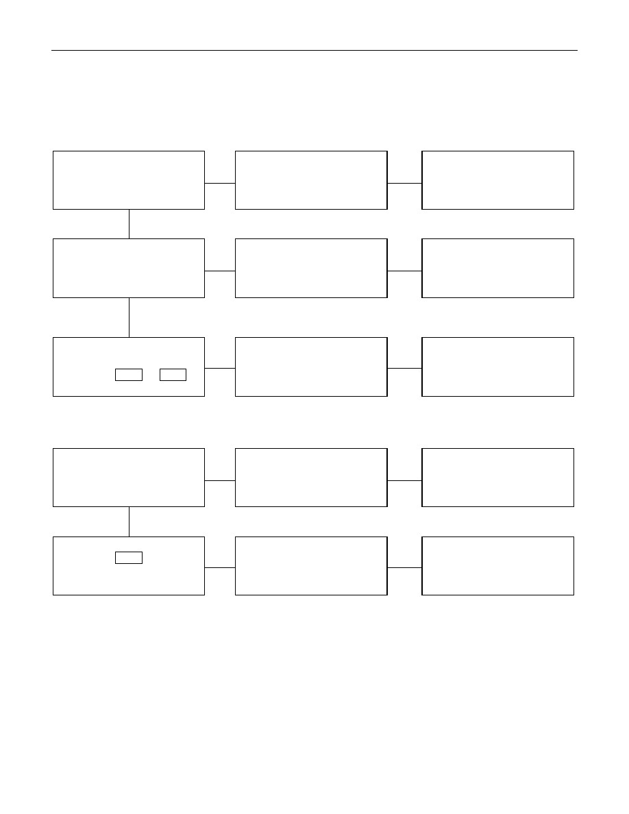
TROUBLE SHOOTING
1. Dome light dose not light
Checkpoint
Trouble Cause
Countermeasure
Replace the dome light bulb
Burned out the bulb
NG
Repair or replace the dome
light assembly
Dome light switch function
Switch malfunction
Repair open circuit or
connector contact
Continuity between
connector 2
H-11
- 1
L-1
Open circuit or poor connector
contact
NG
NG
OK
OK
Dome light bulb continuity
2. Dome light does not go out
Repair or replace the door
switch
Switch malfunction or foreign
material switch
NG
Repair short circuit or
connector contact
Continuity between
connector 1
L-2
-ground
when shutting the door
(Should be no continuity)
Short circuit
NG
OK
Door switch function (Both
side)
ELECTRICAL-BODY AND CHASSIS 8-175
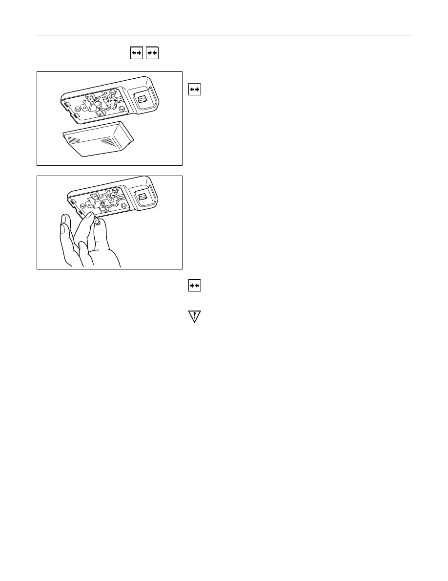
REMOVAL AND INSTALLATION
DOME LIGHT
Removal
1. Remove the dome light lens free.
2. Remove three dome light fixing screws.
3. Remove the wiring connector.
4. Remove the dome light.
5. Pull the bulb to remove it.
Installation
Follow the removal procedure in the reverse order to install the
dome light.
Pay close attention to the important points mentioned in the
following paragraphs.
Bulb
Be absolutely sure that the dome light bulb is correctly
installed.
This will prevent a poor contact and an open circuit.
Нет комментариевНе стесняйтесь поделиться с нами вашим ценным мнением.
Текст