Isuzu D-Max / Isuzu Rodeo (TFR/TFS). Manual — part 810
ENGINE ELECTRICAL (6VD1 3.2L)
6D1–5
Main Data and Specifications
General Specifications
Model (JIS)
95D31R–MF
80D26R–MF
75D26R–MF
Voltage (V)
12
12
12
Cold–Cranking Performance (Amp)
622
582
490
Reserve Capacity (Min)
159
133
123
Load Test (Amp)
310
290
245
Fast Charge Maximum Amperage (Amp)
20
20
20
BCI Group No.
27
24
24

6D2–1
IGNITION SYSTEM (6VD1 3.2L)
ENGINE
IGNITION SYSTEM (6VD1 3.2L)
CONTENTS
Service Precaution
6D2–1
. . . . . . . . . . . . . . . . . . . . . .
General Description
6D2–2
. . . . . . . . . . . . . . . . . . . . .
Diagnosis
6D2–2
. . . . . . . . . . . . . . . . . . . . . . . . . . . . . .
Ignition Coil
6D2–3
. . . . . . . . . . . . . . . . . . . . . . . . . . . . .
Removal
6D2–3
. . . . . . . . . . . . . . . . . . . . . . . . . . . . .
Inspection and Repair
6D2–3
. . . . . . . . . . . . . . . . . .
Installation
6D2–3
. . . . . . . . . . . . . . . . . . . . . . . . . . . .
Spark Plug
6D2–4
. . . . . . . . . . . . . . . . . . . . . . . . . . . . .
Removal
6D2–4
. . . . . . . . . . . . . . . . . . . . . . . . . . . . .
Inspection and Repair
6D2–4
. . . . . . . . . . . . . . . . . .
Installation
6D2–4
. . . . . . . . . . . . . . . . . . . . . . . . . . . .
Crankshaft Angle Sensor
6D2–5
. . . . . . . . . . . . . . . . .
Removal
6D2–5
. . . . . . . . . . . . . . . . . . . . . . . . . . . . .
Installation
6D2–5
. . . . . . . . . . . . . . . . . . . . . . . . . . . .
Main Data and Specifications
6D2–6
. . . . . . . . . . . . .
Service Precaution
WARNING: THIS VEHICLE HAS A SUPPLEMENTAL
RESTRAINT SYSTEM (SRS). REFER TO THE SRS
COMPONENT AND WIRING LOCATION VIEW IN
ORDER TO DETERMINE WHETHER YOU ARE
PERFORMING SERVICE ON OR NEAR THE SRS
COMPONENTS OR THE SRS WIRING. WHEN YOU
ARE PERFORMING SERVICE ON OR NEAR THE SRS
COMPONENTS OR THE SRS WIRING, REFER TO
THE SRS SERVICE INFORMATION. FAILURE TO
FOLLOW WARNINGS COULD RESULT IN POSSIBLE
AIR BAG DEPLOYMENT, PERSONAL INJURY, OR
OTHERWISE UNNEEDED SRS SYSTEM REPAIRS.
CAUTION: Always use the correct fastener in the
proper location. When you replace a fastener, use
ONLY the exact part number for that application.
ISUZU will call out those fasteners that require a
replacement after removal. ISUZU will also call out
the fasteners that require thread lockers or thread
sealant. UNLESS OTHERWISE SPECIFIED, do not
use supplemental coatings (Paints, greases, or other
corrosion inhibitors) on threaded fasteners or
fastener joint interfaces. Generally, such coatings
adversely affect the fastener torque and the joint
clamping force, and may damage the fastener. When
you install fasteners, use the correct tightening
sequence and specifications. Following these
instructions can help you avoid damage to parts and
systems.
INDEX
6D2–2
IGNITION SYSTEM (6VD1 3.2L)
General Description
Ignition is done by the electronic ignition (El) that directly
fires the spark plugs from ignition coils through spark plug
wires without using a distributor. A pair of ignition coils for
the cylinders having different phases by 360
°
(No.1 and
No.4,No.2 and No.5,No.3 and No.6) are fired
simultaneously.
Since the cylinder on exhaust stroke requires less energy
to fire its ignition plug, energy from the ignition coils can be
utilized to fire the mating cylinder on compression stroke.
After additional 360
°
rotation, respective cylinder strokes
are reversed.
The EI consists of six ignition coils,ignition control
module, crank angle sensor, engine control module
(ECM) and other components.
The ignition coils are connected with the ECM by means
of a 32 pin connector.
The ignition control module turns on/off the primary circuit
of ignition coils, and also it controls the ignition timing at
the engine speed below 538 rpm.
A notch in the timing disc on the crankshaft activates the
crank angle sensor which then sends information such as
firing order and starting timing of each ignition coil to the
ECM.
Further, the El employs ignition control (IC) to control
similar to a distributor system.
Diagnosis
Refer to Section Drivability and Emissions for the
diagnosis to electronic ignition system (El system).
6D2–3
IGNITION SYSTEM (6VD1 3.2L)
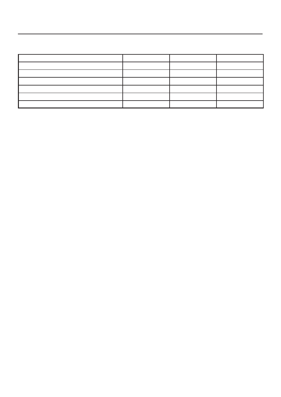
Ignition Coil
Removal
1. Disconnect battery ground cable.
2. Ignition coil connector and ignition coil.
D
Disconnect three connector from ignition coil.
D
Remove harness bracket bolt on cylinder head
cover.
D
Remove fixing bolts on ignition coil.
060RW001
Legend
(1) Ignition Coil Connector
(2) Bolt
(3) Ignition Coil Assembly
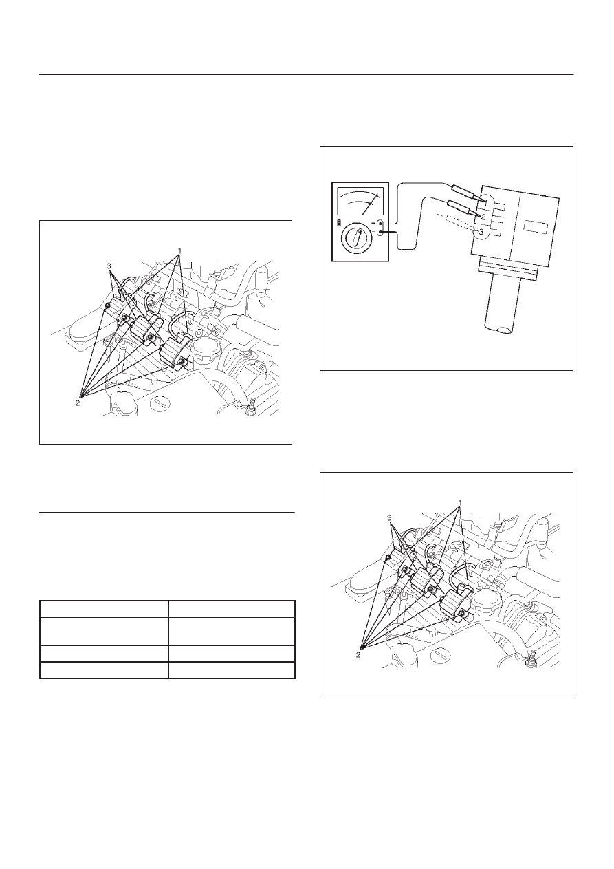
Inspection and Repair
Check the ignition coil assembly for insulation. Check
terminals for corrosion or damage, and replace as
necessary.
Measuring resistance of ignition coil assembly.
Terminal No.
Limit
1 to 2
Without 0 ohm or infinity
maximum ohm.
1 to 3
Same as above
2 to 3
Same as above
Measure resistance of ignition coil assembly, and replace
the ignition coil assembly if its value exceeds the
standard.
060RW006
Installation
1. Install the ignition coil assembly (3).
Connect ignition coil connector (1) and ignition coil
(3), then tighten bolt (2) to the specified torque.
Torque: 4 N·m (0.4 kg·m/35 lb in)
060RW001
2. Connect battery ground cable.
Нет комментариевНе стесняйтесь поделиться с нами вашим ценным мнением.
Текст