Isuzu D-Max / Isuzu Rodeo (TFR/TFS). Manual — part 811
6D2–4
IGNITION SYSTEM (6VD1 3.2L)
Spark Plug
Removal
1. Remove spark plugs.
Inspection and Repair
The spark plug affects entire engine performance and
therefore its inspection is very important.
D
Check electrode and insulator for presence of cracks,
and replace if any.
D
Check electrode for wear, and replace if necessary.
D
Check gasket for damage, and replace if necessary.
D
Measure insulation resistance with an ohmmeter, and
replace if faulty.
D
Adjust spark plug gap to 1.0 mm (0.04 in)
∼
1.1 mm
(0.043 in).
D
Check fuel and electrical systems if spark plug is
extremely dirty.
D
Use spark plugs having low heat value (hot type plug)
if fuel and electrical systems are normal.
D
Use spark plugs having high heat value (cold type
plug) if insulator and electrode are extremely burned.
Sooty Spark Plugs
Much deposit of carbon or oil on the electrode and
insulator of spark plug reduces the engine performance.
Possible causes:
D
Too rich mixture
D
Presence of oil in combustion chamber
D
Incorrectly adjusted spark plug gap
Burning Electrodes
This fault is characterized by scorched or heavily oxidized
electrode or blistered insulator nose.
Possible causes:
D
Too lean mixture
D
Improper heat value
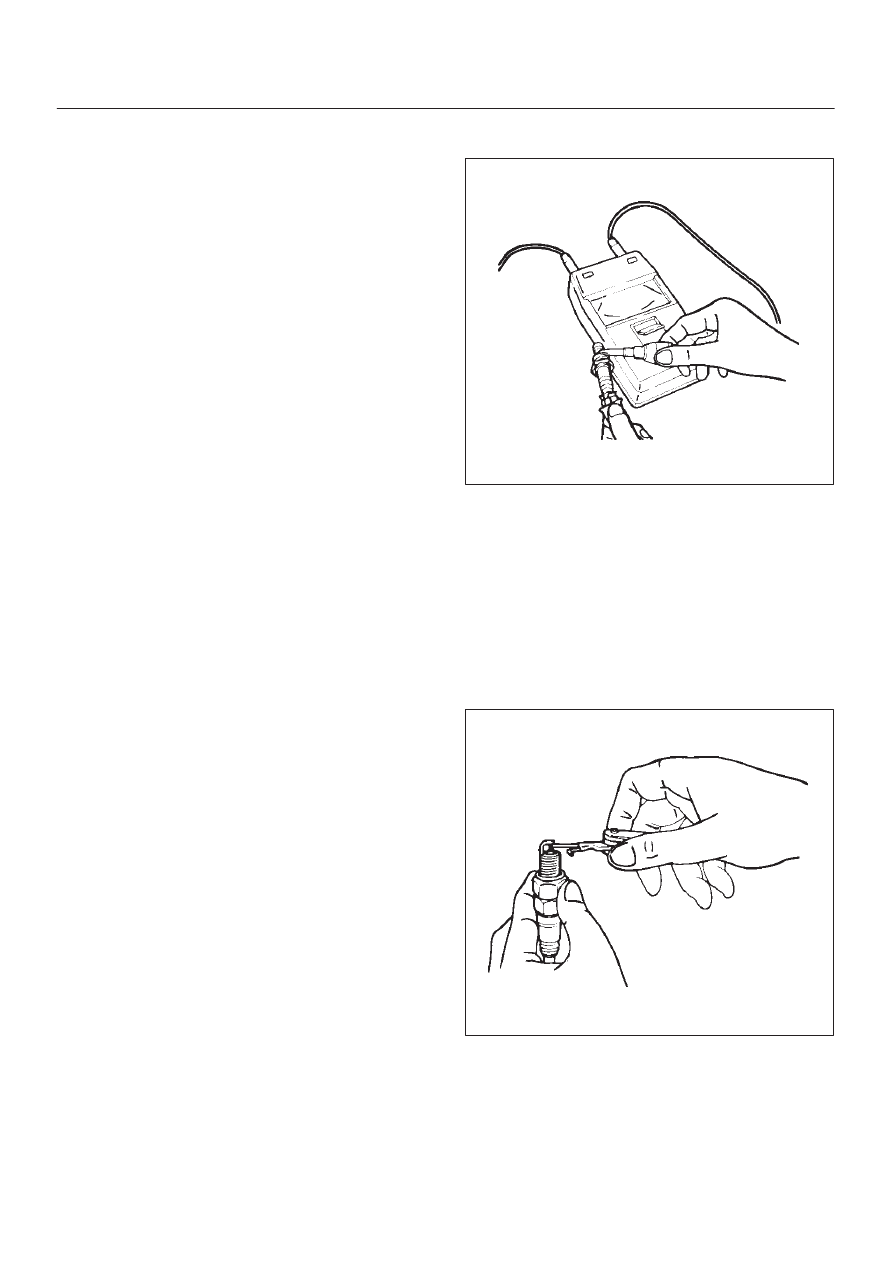
Measuring Insulation Resistance
D
Measure insulation resistance using a 500 volt
megaohm meter.
D
Replace spark plugs if measured value is out of
standard.
Insulation resistance: 50 M
W
or more
011RS010
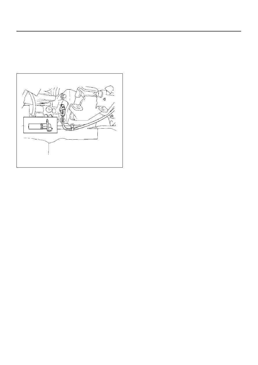
Cleaning Spark Plugs
D
Clean spark plugs with a spark plug cleaner.
D
Raise the ground electrode to an angle of 45 to 60
degrees. If electrode is wet, dry it before cleaning.
D
After spark plug is thoroughly cleaned, check
insulator for presence of cracks.
D
Clean threads and metal body with a wire brush.
D
File the electrode tip if electrode is extremely worn.
D
Bend the ground electrode to adjust the spark plug
gap.
011RS011
Installation
1. Spark plugs
D
Tighten spark plugs to the specified torque.
Torque: 18 N·m (1.8 kg·m/13 lb ft)
6D2–5
IGNITION SYSTEM (6VD1 3.2L)
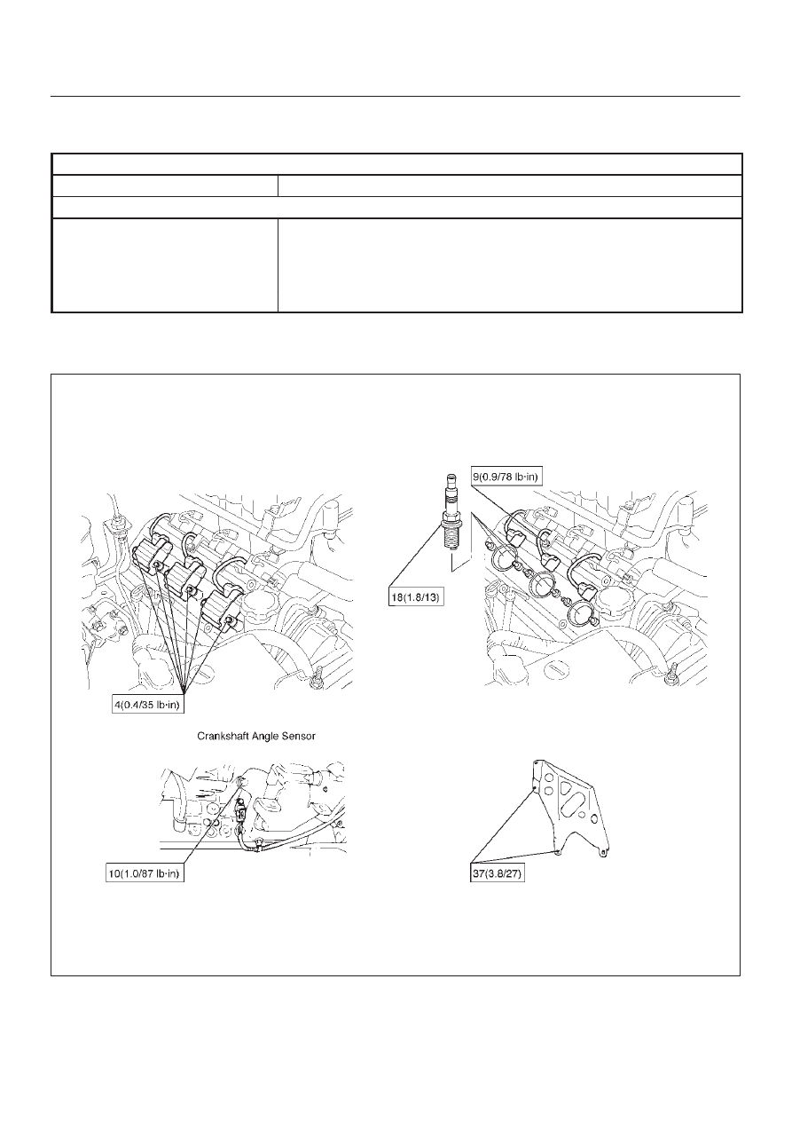
Crankshaft Angle Sensor
Removal
1. Disconnect battery ground cable
2. Wiring connector from crankshaft angle sensor.
3. Remove crankshaft angle sensor from cylinder block.
012RS008
Installation
1. Install crankshaft angle sensor into the cylinder block.
Before installation,apply small amount of engine oil to
the O–ring.
Torque: 10 N·m (1.0 kg·m/89 lb in)
2. Reconnect wiring connector to crankshaft angle
sensor.
6D2–6
IGNITION SYSTEM (6VD1 3.2L)
Main Data and Specifications
General Specifications
Ignition System
Ignition Form
Electronic Ignition System (El system) with Crankshaft angle Sensor
Spark Plug
Type
K16PR–P11
RC10PYP4
PK16PR11
Plug gap
1.0 mm (0.04 in) – 1.1 mm (0.043 in)
Torque
18 N·m (13lb ft)
Torque Specifications
N·m (kg·m/ lb·ft)
E06RW038

6D3–1
STARTING AND CHARGING SYSTEM (6VD1 3.2L)
ENGINE
STARTING AND CHARGING SYSTEM (6VD1 3.2L)
CONTENTS
Service Precaution
6D3–1
. . . . . . . . . . . . . . . . . . . . . .
Starting System
6D3–2
. . . . . . . . . . . . . . . . . . . . . . . . .
General Description
6D3–2
. . . . . . . . . . . . . . . . . . . . .
Diagnosis
6D3–4
. . . . . . . . . . . . . . . . . . . . . . . . . . . . . .
Starter
6D3–5
. . . . . . . . . . . . . . . . . . . . . . . . . . . . . . . . .
Removal
6D3–5
. . . . . . . . . . . . . . . . . . . . . . . . . . . . .
Installation
6D3–5
. . . . . . . . . . . . . . . . . . . . . . . . . . . .
Disassembled View
6D3–6
. . . . . . . . . . . . . . . . . . . .
Disassembly
6D3–7
. . . . . . . . . . . . . . . . . . . . . . . . . .
Inspection and Repair
6D3–9
. . . . . . . . . . . . . . . . . .
Reassembly
6D3–13
. . . . . . . . . . . . . . . . . . . . . . . . . .
Main Data and Specifications
6D3–15
. . . . . . . . . . .
Charging System
6D3–17
. . . . . . . . . . . . . . . . . . . . . . . .
General Description
6D3–17
. . . . . . . . . . . . . . . . . . . . .
General On–Vehicle Inspection
6D3–17
. . . . . . . . . . .
Generator
6D3–18
. . . . . . . . . . . . . . . . . . . . . . . . . . . . . .
Removal
6D3–18
. . . . . . . . . . . . . . . . . . . . . . . . . . . . .
Inspection
6D3–18
. . . . . . . . . . . . . . . . . . . . . . . . . . . .
Installation
6D3–18
. . . . . . . . . . . . . . . . . . . . . . . . . . . .
Disassembled View
6D3–19
. . . . . . . . . . . . . . . . . . . .
Disassembly
6D3–19
. . . . . . . . . . . . . . . . . . . . . . . . . .
Inspection and Repair
6D3–22
. . . . . . . . . . . . . . . . . .
Reassembly
6D3–24
. . . . . . . . . . . . . . . . . . . . . . . . . .
Bench Test
6D3–24
. . . . . . . . . . . . . . . . . . . . . . . . . . .
Main Data and Specifications
6D3–25
. . . . . . . . . . .
Service Precaution
WARNING: THIS VEHICLE HAS A SUPPLEMENTAL
RESTRAINT SYSTEM (SRS). REFER TO THE SRS
COMPONENT AND WIRING LOCATION VIEW IN
ORDER TO DETERMINE WHETHER YOU ARE
PERFORMING SERVICE ON OR NEAR THE SRS
COMPONENTS OR THE SRS WIRING. WHEN YOU
ARE PERFORMING SERVICE ON OR NEAR THE SRS
COMPONENTS OR THE SRS WIRING, REFER TO
THE SRS SERVICE INFORMATION. FAILURE TO
FOLLOW WARNINGS COULD RESULT IN POSSIBLE
AIR BAG DEPLOYMENT, PERSONAL INJURY, OR
OTHERWISE UNNEEDED SRS SYSTEM REPAIRS.
CAUTION: Always use the correct fastener in the
proper location. When you replace a fastener, use
ONLY the exact part number for that application.
ISUZU will call out those fasteners that require a
replacement after removal. ISUZU will also call out
the fasteners that require thread lockers or thread
sealant. UNLESS OTHERWISE SPECIFIED, do not
use supplemental coatings (Paints, greases, or other
corrosion inhibitors) on threaded fasteners or
fastener joint interfaces. Generally, such coatings
adversely affect the fastener torque and the joint
clamping force, and may damage the fastener. When
you install fasteners, use the correct tightening
sequence and specifications. Following these
instructions can help you avoid damage to parts and
systems.
INDEX
Нет комментариевНе стесняйтесь поделиться с нами вашим ценным мнением.
Текст