Isuzu D-Max / Isuzu Rodeo (TFR/TFS). Manual — part 938

PROPELLER SHAFT 4A-7
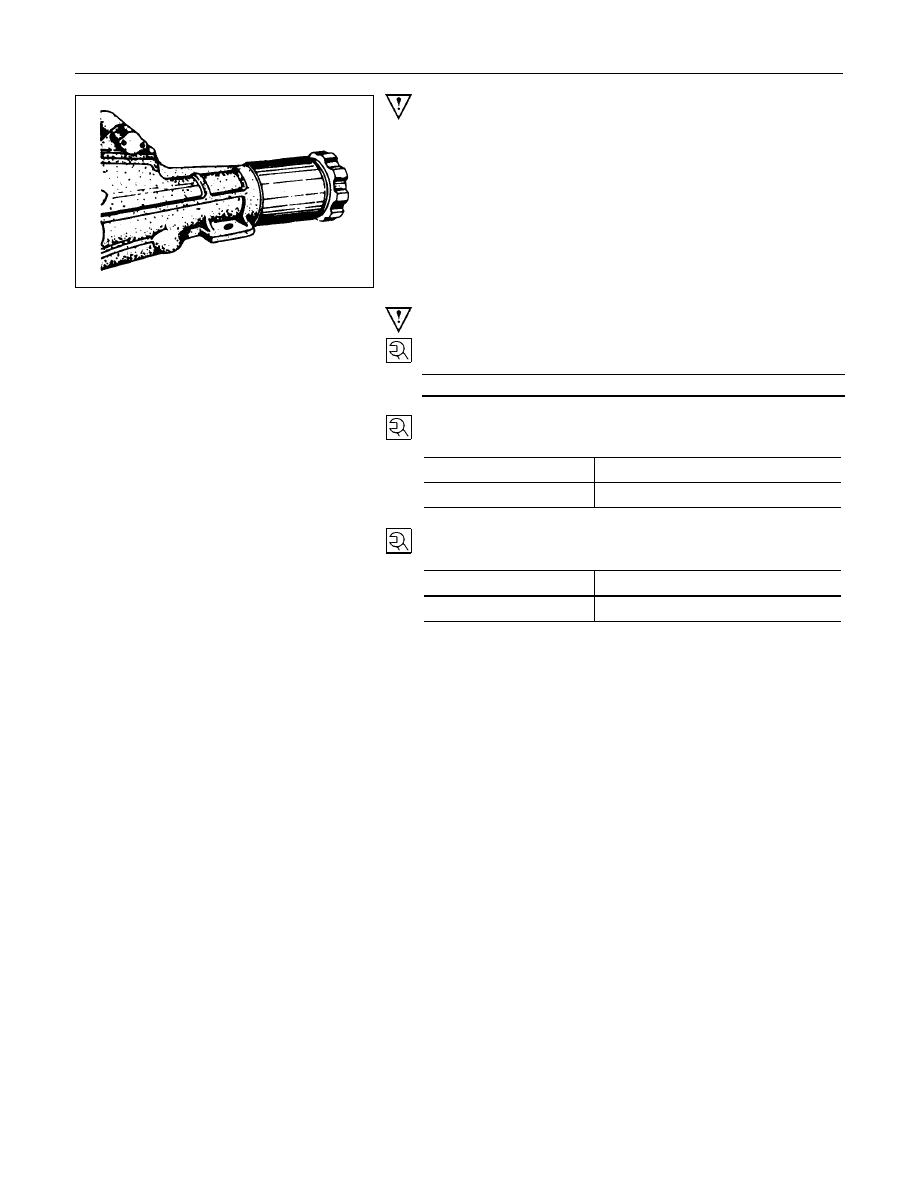
REMOVAL AND INSTALLATION
Since the propeller shaft assembly is carefully
balanced, a scribe mark should be made on
the flange before removal.
Install the parts by aligning scribe marks made
during removal.
Removal Steps
1. 1a. Bolt ; differential side
2. Bolt ; flange
▲
2a. Propeller shaft assembly
3. Propeller shaft assembly ; 2nd
4. Bolt ; center bearing bracket
▲
5. Propeller shaft assembly ; 1st
Installation Steps
5. Propeller assembly ; 1st
▲
4. Bolt ; center bearing bracket
3. Propeller shaft assembly ; 2nd
▲
2. Bolt ; flange
2a. Propeller shaft assembly
▲
1. 1a. Bolt ; differential side
4A-8 PROPELLER SHAFT
Important Operations - Removal
2a.Propeller Shaft Assembly
5. Propellers Shaft Assembly ; 1st
Install a plug at the transmission rear cover to prevent loss of
the transmission oil.
Important Operations - Installation
4. Bolt ; Center Bearing Bracket
Bolt Torque
N
⋅
m (kgf
⋅
m/lb
⋅
ft)
68.6
±
13.7 (7.0
±
1.4 / 50.4
±
10)
2. Bolt ; Flange
Bolt Torque
N
⋅
m (kgf
⋅
m/lb
⋅
ft)
Bolt size M10
62.8
±
3.9 (6.4
±
0.4/46.3
±
2.9)
Bolt size M8
35.3
±
2.9 (3.6
±
0.3/26
±
2.2)
1. 1a. Bolt ; differential side
Bolt Torque
N
⋅
m (kgf
⋅
m/lb
⋅
ft)
Bolt size M10
62.8
±
3.9 (6.4
±
0.4/46.3
±
2.9)
Bolt size M8
35.3
±
2.9 (3.6
±
0.3/26
±
2.2)

PROPELLER SHAFT 4A-9
DISASSEMBLY
UNIVERSAL JOINT
Disassembly Steps
1. Snap ring
2. Needle roller bearing
3. Spider
4. Flange yoke
Reassembly steps
To reassemble, follow the disassembly steps
in the reverse order.
Important Operation
1. Snap ring
•
Apply alignment marks on the yokes of the universal
joint.
2. Needle roller bearing
•
Tap out the bearing by gently striking the shoulder of the
yoke, using a mallet or a copper hammer.
3. Spider
•
Make sure of proper position for reinstallation by
applying setting marks.
4. Flange Yoke

4A-10 PROPELLER SHAFT
INSPECTION AND REPAIR
Make all necessary adjustment, repairs, and part replacements if wear, damage, or other problems are discovered
during inspection.
Spider
Needle roller bearing
Yoke
Flange
Center bearing
Cushioning rubber
Bracket
Visual Check
Inspect following parts for wear, damage, or other abnormal
conditions.
Outside Diameter of Spider Pins
mm(in)
Standard
Limit
17 (0.67)
16.90 (0.665)
Propeller Shaft Run-Out
Support the ends of the propeller shaft on V-blocks and check
for run-out by holding the probe of a dial indicator in contact
with the center part of the shaft.
If the amount of run-out is beyond the standard value for
assembly, correct with a bench press or replace the shaft with
a new one.
mm(in)
Standard
Limit
17 (0.67)
16.90 (0.665)
Нет комментариевНе стесняйтесь поделиться с нами вашим ценным мнением.
Текст