Isuzu D-Max / Isuzu Rodeo (TFR/TFS). Manual — part 382
7A-76 AUTOMATIC TRANSMISSION (AW30-40LE)
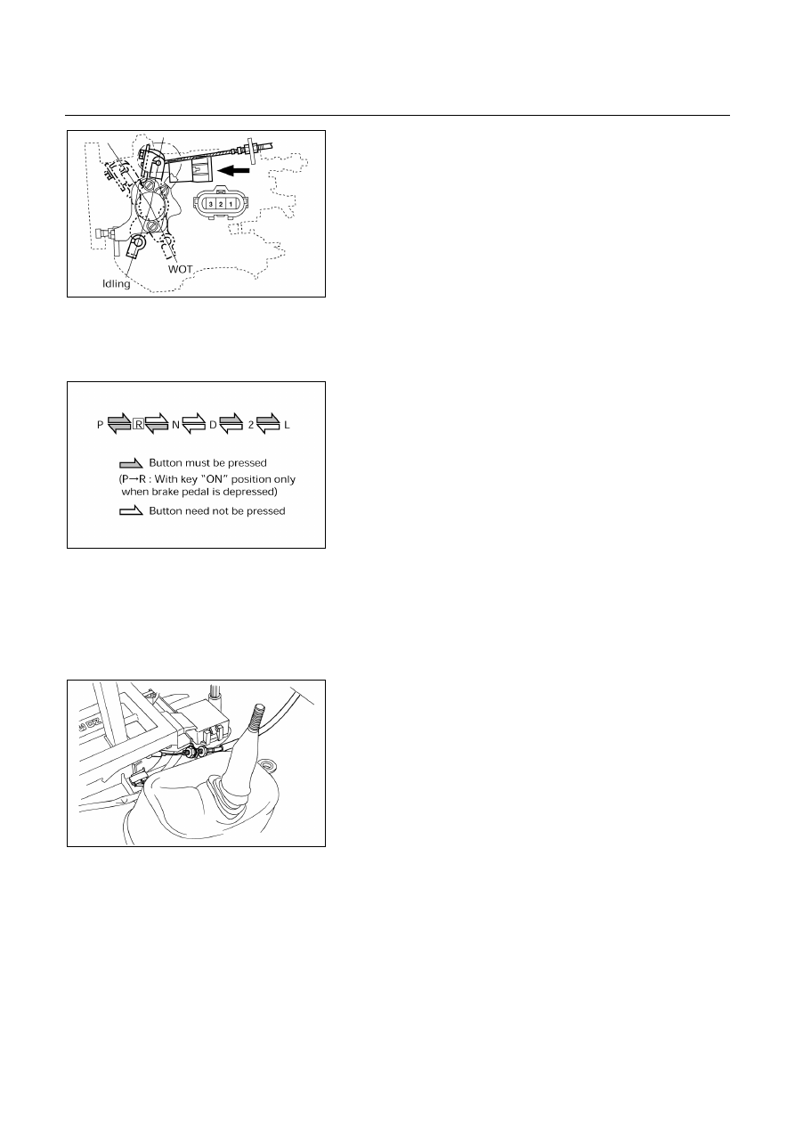
THROTTLE POSITION SENSOR
INSPECTION
1. Turn the starter switch to the “ON” position.
2. Measure the voltage between throttle position sensor
connector terminals 2 (output) and 3 (ground).
NOTE:
・ Do not remove the sensor connector.
・ Make sure that power source (7 – 8V) is measured
between terminals 1 and 3 before measurement at
step 2.
Standard voltage:
Idling −
−
−
− 0.24 – 1.30V
WOT −
−
−
− 5.30 – 7.50V
101R200003
256RY00001
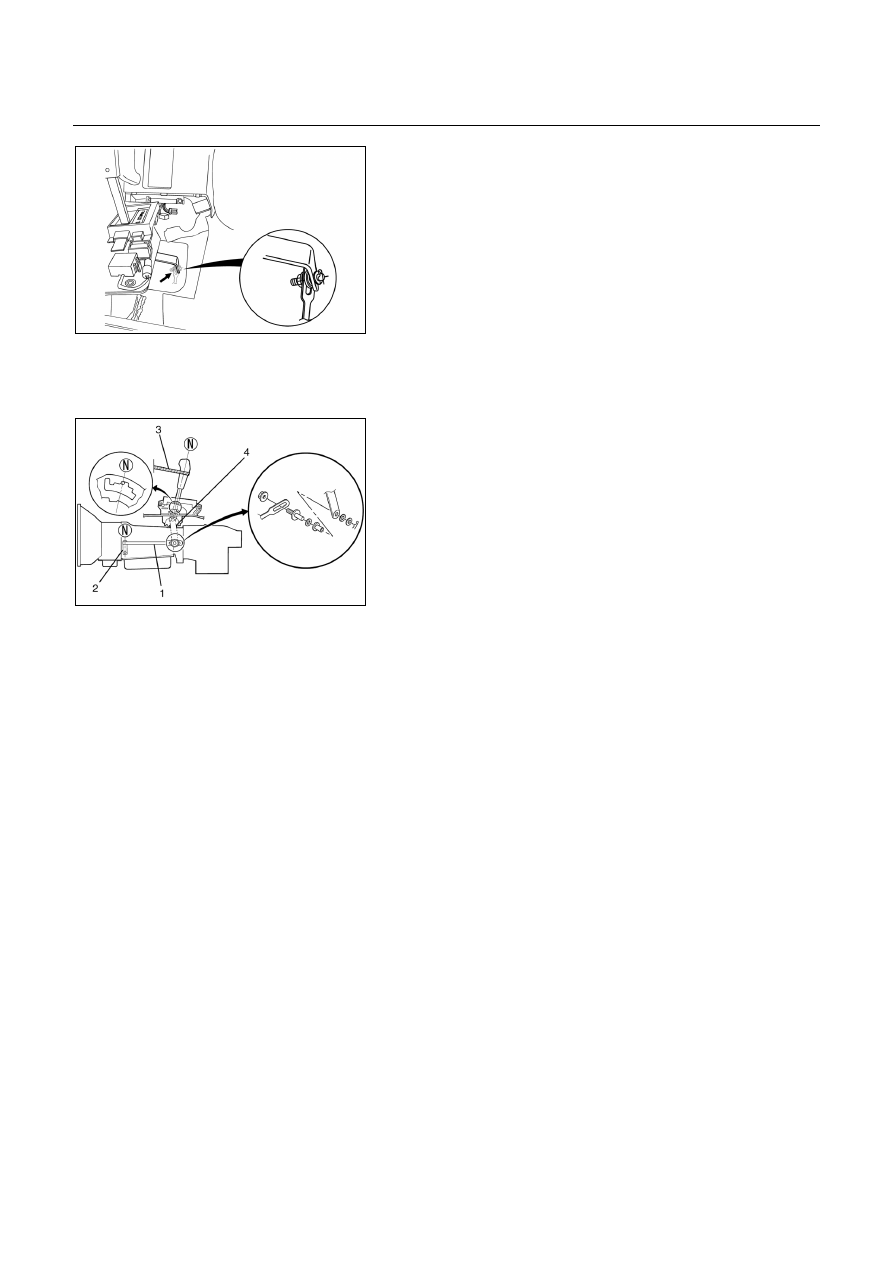
SELECTOR LEVER
Inspection
1. Make sure that when the selector lever is shifted from
"P" to "L", a "clicking" can be felt at each shift position.
Make sure that the gear corresponds to that of the
position plate indicator.
2. Check to see if the selector lever can be shifted as
shown.
REMOVAL
Preparation:
Disconnect negative (-) battery cable.
1. Transfer Control Lever Knob (4×4)
2. Front
Console
Disconnect wiring harness connectors.
(4×
×
×
×4)
256RW012
3. Selector Lever Assembly
1. Disconnect shift lock cable from the selector lever
assembly side.
2. Disconnect wiring harness connectors.
AUTOMATIC TRANSMISSION (AW30-40LE) 7A-77
256RW013
3. Disconnect shift control rod from the selector lever
assembly side.
INSTALLATION
To install, follow the removal steps in the reverse order,
noting the following points;
256RW014
Adjustment of select lever and control rod
1. Place the vehicle on a level surface.
NOTE:
If the vehicle is not on a level surface, the shift
select cable set position will vary with the
movement of the engine. To prevent possible
misadjustment of the cable, the vehicle must be
placed on a level surface.
2. Install the shift control rod (1) to the transfmission
select lever (2), and then place the lever in the "N"
position.
3. Set select lever in the "N" position.
4. Push selector lever forward and secure it (using a
rubber band (3), etc.) so that pin comes into contact
with the wall of detent plate.
5. Install the shift control rod (1) to the selector lever arm
(4).
Nut torque: 27 N・・・・m (2.8 kg・・・・m/20 Ib・・・・ft)
NOTE:
Do not apply oil to threaded portions.
6. After adjustment, operate select lever on a trial basis to
makes sure of its smooth operation and no abnormal
indication in each position.
7A-78 AUTOMATIC TRANSMISSION (AW30-40LE)
256RW015
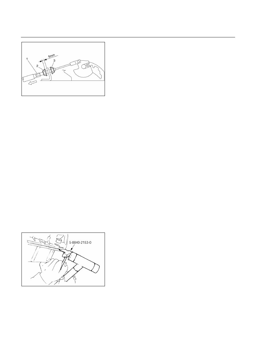
Adjustment of shift lock cable
1. Set ignition key in "LOCK" position and selector lever in
"P" position.
2. Adjust cable screw cap on selector lever side to provide
a gap (slack for cable) of 1-2mm between rod on
steering lock side and stopper
Adjust cap as follows:
a. Pull screw cap (1) in arrow direction to put off slack of
inner cable.
b. With cable kept as (a), adjust gap between nut (2)
and bracket to 5mm (0.2in).
c. Lock inner cable by turning nut (3) while holding nut
(2) in place.
Lock nut torque: 3.7 N・・・・m (38 kg・・・・cm/33 Ib・・・・in)
NOTE:
Clean the rod threads and do not apply oil to the
threaded portions.
3. Make sure of proper operation of shift lock through
checks as follows:
a. Selector lever shall not be moved out of "P" position
with ingition key in "Lock" position.
b. Selector lever can be moved out of "P" position with
ignition key in "ON" position only when brake pedal is
depressed.
c. Ignition key can be turned to "LOCK" position only
when selector lever is in "P" position (key can be
pulled out).
If (a) and (c) fail, readjust cable. If (b) fails, readjust
connector wiring and brake pedal switch.
240RY00007
SHIFT SOLENOID AND LOCK-UP
SOLENOID
REMOVAL
Preparation:
・ Disconnect negative (-) battery cable.
・ Drain the fluid
1. Remove the nineteen bolts and oil pan.
Seal cutter: 5-8840-2153-0
AUTOMATIC TRANSMISSION (AW30-40LE) 7A-79
240RY00008
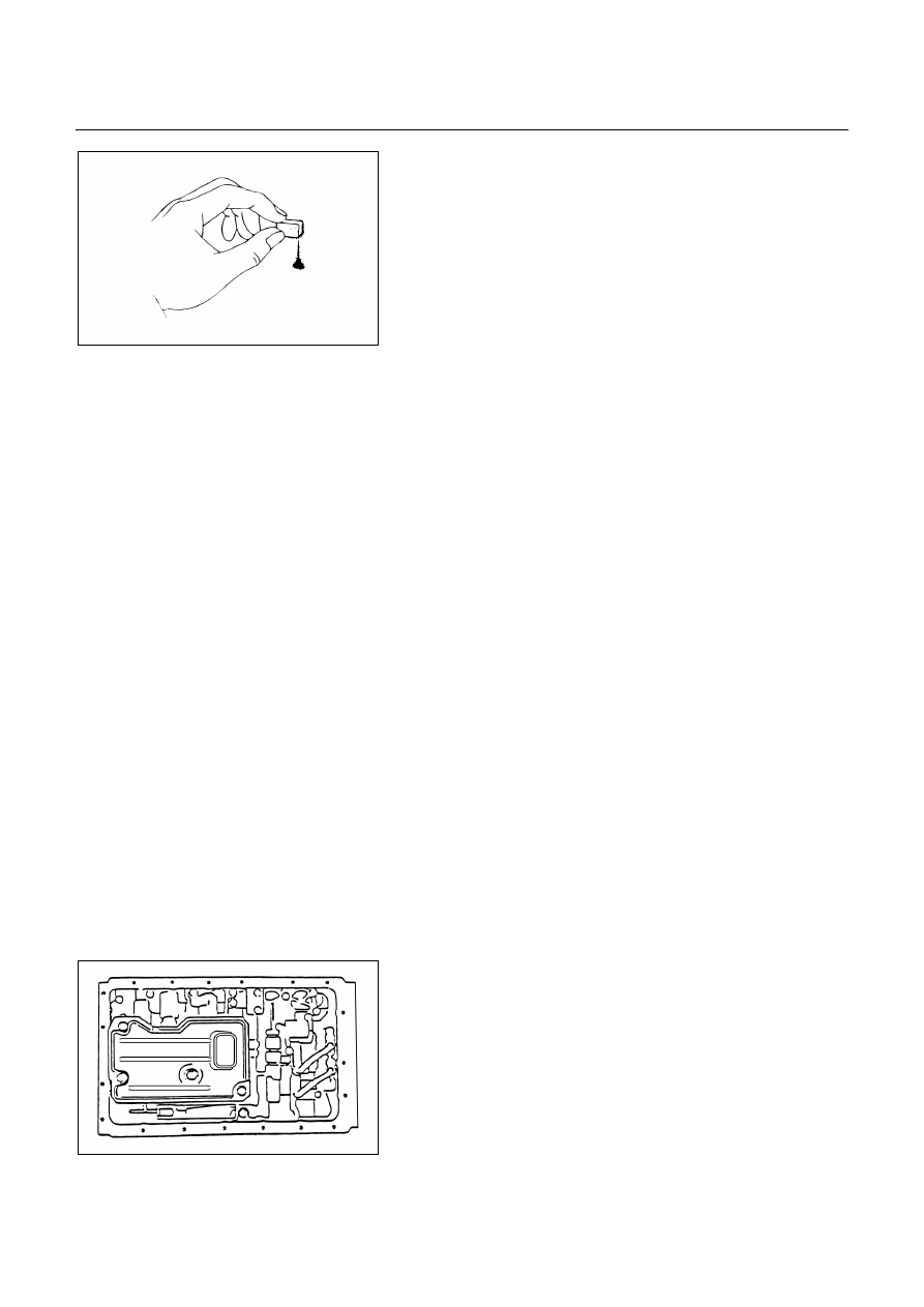
Examine particles in pan
Remove the magnet and use it to collect any steel
chips. Look carefully at the chips and particles in the
pan and on the magnet to anticipate what type of wear
you will find in the transmission:
Steel (magnetic). .bearing, gear and clutch plate wear
Brass (non-magnetic)...bushing wear
2. Disconnect the solenoid wiring connectors from the
shift solenoid S1, S2 and lock-up solenoid S3.
3. Remove each retaining bolts and solenoids.
INSTALLATION
To install, follow the removal steps in reverse order noting
the following point.
1. Solenoid retaining bolt
Torque: 10 N・・・・m (1.0 kg・・・・m/87 Ib・・・・in)
2. Oil
pan
bolts
Torque: 8 N・・・・m (0.8 kg・・・・m/69 Ib・・・・in)
VALVE BODY ASSEMBLY
REMOVAL
Preparation:
・ Disconnect negative (-) battery cable.
・ Drain the fluid
1. Remove the nineteen bolts and oil pan.
Seal cutter: 5-8840-2153-0
・ Examine particles in pan.
Refer to “SHIFT SOLENOID AND LOCK-UP
SOLENOID”.
244R200001
2. Remove four retaining bolts and oil strainer.
Нет комментариевНе стесняйтесь поделиться с нами вашим ценным мнением.
Текст