Isuzu D-Max / Isuzu Rodeo (TFR/TFS). Manual — part 380
7A-68 AUTOMATIC TRANSMISSION (AW30-40LE)
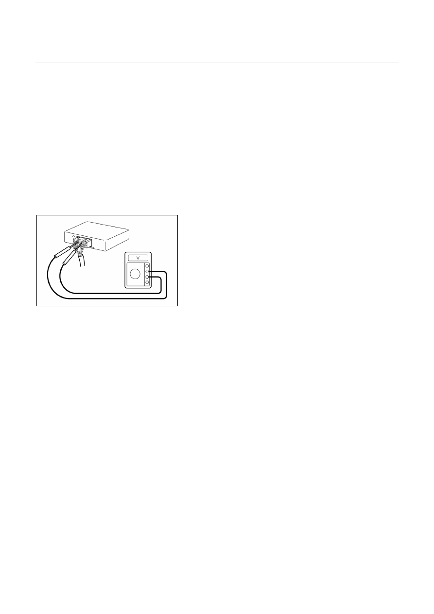
TCM VOLTAGE CHECK
TCM voltage check is done to check for transmission and
transmission control module (TCM) problems which cannot
be detected by self-diagnosis.
Additionally, it serves as a back-up check for self-
diagnosis.
Measure the voltage drop and make a continuity test for
each of the sensors, solenoids, and switches.
If the voltage is within the specified range and continuity
exists, that particular area of the TCM and automatic
transmission assembly is normal.
If voltage deviation or lack of continuity is discovered,
disconnect the applicable parts and check each of them
individually.
This will allow you to determine the trouble location (TCM,
automatic transmission unit, or another area of the
vehicle).
826L100005
Inspection Tool
Use a circuit tester to measure voltage and circuit
continuity.
Insert the test probes from the connector wiring side. TCM
terminals are extremely small.
Wrap a piece of thin wire around the probe of tester.
This will make measurement easier.
NOTE:
TCM is located in the behind instrument panel of the
driver’s compartment.
TCM Voltage Check Procedure
1. Remove the TCM.
2. Turn the ignition switch on. Do not start the engine.
3. Measure the voltage at the terminal.
Refer the following table for the specified voltage
ranges.

AUTOMATIC TRANSMISSION (AW30-40LE) 7A-69
TCM STANDARD VOLTAGE
[26 PIN CONNECTOR]
Terminal
Check circuit
+ –
Measuring condition
Voltage (V)
Throttle fully opened
5.3 – 7.5
Throttle position sensor
18 24
Throttle fully closed (idling)
0.24 – 1.3
Vehicle speed sensor 1
6
24 Vehicle speed 10 – 20 km/h
Less than 1.4 ⇔ About 5
Vehicle speed sensor 2
22 23 Vehicle speed 10 – 20 km/h
0 ⇔ About 3
Selector “2” range
7 – 16
2 range switch
2
24
Selector all ranges except “2”
Less than 1
Selector “L” range
7 – 16
L range switch
1
24
Selector all ranges except “L”
Less than 1
Pattern select switch OFF (NORMAL)
8 – 16
Pattern select switch
16 24
Pattern select switch ON (POWER)
Less than 1
Depress brake
7 – 16
Brake switch
14 24
Release brake
Less than 1
O/D switch position OFF
(O/D OFF lamp ON)
7 – 16
O/D switch
15 24
O/D switch position ON
(O/D OFF lamp OFF)
Less than 1
OFF (3rd or O/D)
Less than 1
Shift solenoid S1
13 24
ON (1st or 2nd)
8 – 16
OFF (1st or O/D)
Less than 1
Shift solenoid S2
12 24
ON (2nd or 3rd)
8 – 16
OFF (Lock-up OFF)
Less than 1
Lock-up control solenoid S3 11 24
ON (Lock-up ON)
8 – 16
Diagnosis terminal
21 24 Self-diagnosis ON
0 – 1.5
Electrical source (Battery)
25 24
―
9 – 16
Electrical source (Ignition)
26 24 Key switch ON
9 – 16
Selector “N” range
7 – 16
N range switch
3
24
Selector all ranges except “N”
Less than 1
ATF temperature 20℃
4.70
ATF fluid temperature
sensor
20 8
ATF temperature 80℃
3.65
OFF
8 – 16
Winter select switch (UBS)
4
24
ON
Less than 1
ON
Less than 1
Power lamp
5
24
OFF
8 – 16
ON
Less than 1
Winter lamp (UBS)
7
24
OFF
8 – 16
ON
Less than 1
CHECK TRANS lamp
19 24
OFF
8 – 16
Tech 2 diagnosis terminal
(DG)
10 24 On diagnosis communication
0 – 1.5 ⇔ 6.25 – 8.0

7A-70 AUTOMATIC TRANSMISSION (AW30-40LE)
ON-VEHICLE SERVICE
242RX00001
TRANSIMISSION FLUID LEVEL AND
CONDITION
Park vehicle on level ground and set parking brake.
With the engine idling, move the shift lever through all
positions from "P" to "L", then return to position "P".
Check to see If the level of fluid comes to "HOT" range of
about 80
°C (176°F) on the dipstick gauge.
If the level of fluid is too low, replenish to bring it to
maximum level in "HOT" range.
Inspection of fluid condition
If the ATF is black or smells burnt, replace it.
ATF REPLACEMENT
NOTE:
Do not overfill.
1. Remove the drain plug from oil pan and drain the fluid.
2. Reinstall the drain plug securely.
Torque: 19 N・・・・m (1.9 kg・・・・m/14 Ib・・・・ft)
3. With the engine OFF, add new fluid through the filler
tube.
Drain and refill
4.5 liter
Dry fill
8 liter
Fluid
BESCO ATF Ⅲ
4. Start the engine and shift the selector into all position
from "P" through "L", and then shift into "P".
5. With the engine idling, check the fluid level. Add fluid up
to the "COLD" level on the dipstick.
6. The ATF level must be checked again for correct level
with the "HOT" level.
NOTE:
To prevent fluid leaks, the drain plug gasket must be
replaced each time this plug is removed.

AUTOMATIC TRANSMISSION (AW30-40LE) 7A-71
THROTTLE CABLE ADJUSTMENT
1. Check that the idling set bolt comes into contact with
control lever.
2. Measure the distance (C) between the end of the boot
and stopper on the cable (1).
Standard distance (C): 0.5 – 1.5 m (0.03 – 0.06 in)
If the distance is not within the standard, adjust the
cable by the adjust nuts.
3. Fully depress the accelerator, check that the control
lever comes into contact with the full stopper.
4. Measure the control lever stroke (S).
+1 +0.04
Standard stroke (S): 32.9
0
mm (1.30
0
in)
101R200001
If the stroke is not within the standard, adjust the
turning radius of control lever (3) by bolt (2).
S < 32.9 →
→
→
→ Turning radius is enlarged.
S > 33.9 →
→
→
→ Turning radius is made small.
5. Recheck
the
adjustments.
Нет комментариевНе стесняйтесь поделиться с нами вашим ценным мнением.
Текст