Isuzu D-Max / Isuzu Rodeo (TFR/TFS). Manual — part 1273
8–12 ELECTRICAL-BODY AND CHASSIS
FUSE
Fuses are the most common form of circuit protection
used in vehicle wiring. A fuse is a thin piece of wire or
strip of metal encased in a glass or plastic housing. It is
wired in series with the circuit it protects. When there is
an overload of current in a circuit, such as a short of a
ground, the wire or metal strip is designed to burn out
and interrupt the flow of current. This prevents a surge of
high current from reaching and damaging other
components in the circuit.
Determine the cause of the overloaded before replacing
the fuse.
Never replace a blown fuse with a fuse of a different
amperage specification.
Doing so can result in an electrical fire or other serious
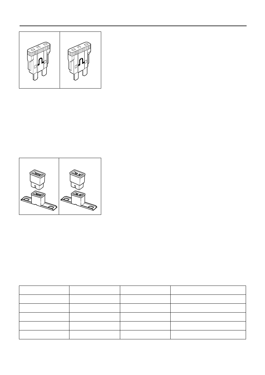
circuit damage. A blown fuse is easily identified.
Normal
Blown
D08RV684
FUSIBLE LINK
The fusible link is primarily used to protect circuits where
high amounts of current flow and where is would not be
practical to use a fuse. For example, the starter circuit.
When a current overload occurs, the fusible link melts
open and interrupts the flow of current so as to prevent
the rest of the wiring harness from burning.
Determine the cause of the overload before replacing the
fusible link. The replacement fusible link must have the
same amperage specification as the original fusible link.
Never replace a blown fusible link with fusible link of a
different amperage specification. Doing so can result in
an electrical fire or other serious circuit damage.
A blown fusible link is easily identified.
Normal
Blown
Fusible Link Specifications
Type
Rating
Case Color
Maximum Circuit Current (A)
Connector
30A
Pink
15
Connector
40A
Green
20
Bolted
50A
Red
25
Bolted
60A
Yellow
30
Bolted
80A
Black
40
ELECTRICAL-BODY AND CHASSIS 8–13
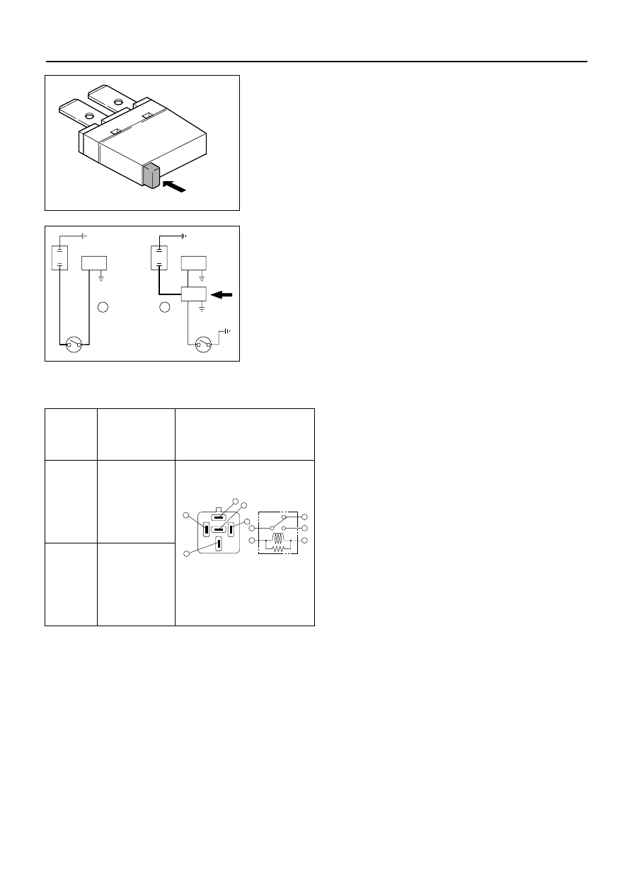
CIRCUIT BREAKER
The circuit breaker is a protective device designed to
open the circuit when a current load is in excess of rated
breaker capacity. If there is a short or other type of
overload condition in the circuit, the excessive current
will open the circuit between the circuit breaker terminals.
The reset knob pops out when the circuit is open. Push
the reset knob in place to restore the circuit after repairing
it.
Push
RELAY
Battery and load location may require that a switch be
placed some distance from either component. This
means a longer wire and a higher voltage drop 1. The
installation of a relay between the battery and the load
reduces the voltage drop 2.
Because the switch controls the relay, amperage through
the switch can be reduced.
Relay Specifications and Configurations
* Relay contact shown in the wiring diagram indicates condition before actuation.
1
2
RELAY
LOAD
LOAD
D08RV709
060RV005
Rated
Name/
voltage/
Internal circuit
Color
Coil
resistance
12V
1T
Approx. 90
Ω
(MR5C)/
Minimum
Black
operating
voltage: 7V
at 25°C(77°F)
12V
1T
Approx. 90
Ω
(MR5C)/
Minimum
Brown
operating
voltage: 10.5V
at 25°C(77°F)
4
1
3
2
5
2
1
3
4
5
8–14 ELECTRICAL-BODY AND CHASSIS
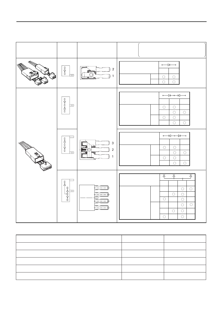
DIODE
Diode Specifications and Configurations
SHAPE
MARK/
COLOR
CONSTRUCTION
CHECKING
BLACK
BLACK
CONNECTION
PATTERN
2
1
A
B
+
–
BLACK
3
2
1
3
2
1
+
–
+
–
+
–
+
–
+
–
+
–
+
–
+
–
+
–
4
3
2
+
–
+
1
–
+
–
–
+
+
–
+
–
BLACK
4
3
2
1
THERE SHOULD BE CONTINUITY IN
EITHER A OR B WHEN A CIRCUIT
TESTER IS CONNECTED WITH
DIODE TERMINAL
TERMINAL NO.
CONNECTION
PATTERN
A
B
TERMINAL NO.
CONNECTION
PATTERN
A
B
TERMINAL NO.
CONNECTION
PATTERN
A
B
TERMINAL NO.
Maximum Rating (Temp.=25°C)
Items
Rating
Remarks
Peak reverse voltage
400V
Transient peak reverse voltage
500V
Average output current
1.5A
Temp.=40°C
Working ambient temperature
–30°C~80°C
Storage temperature
–40°C~100°C
ELECTRICAL-BODY AND CHASSIS 8–15
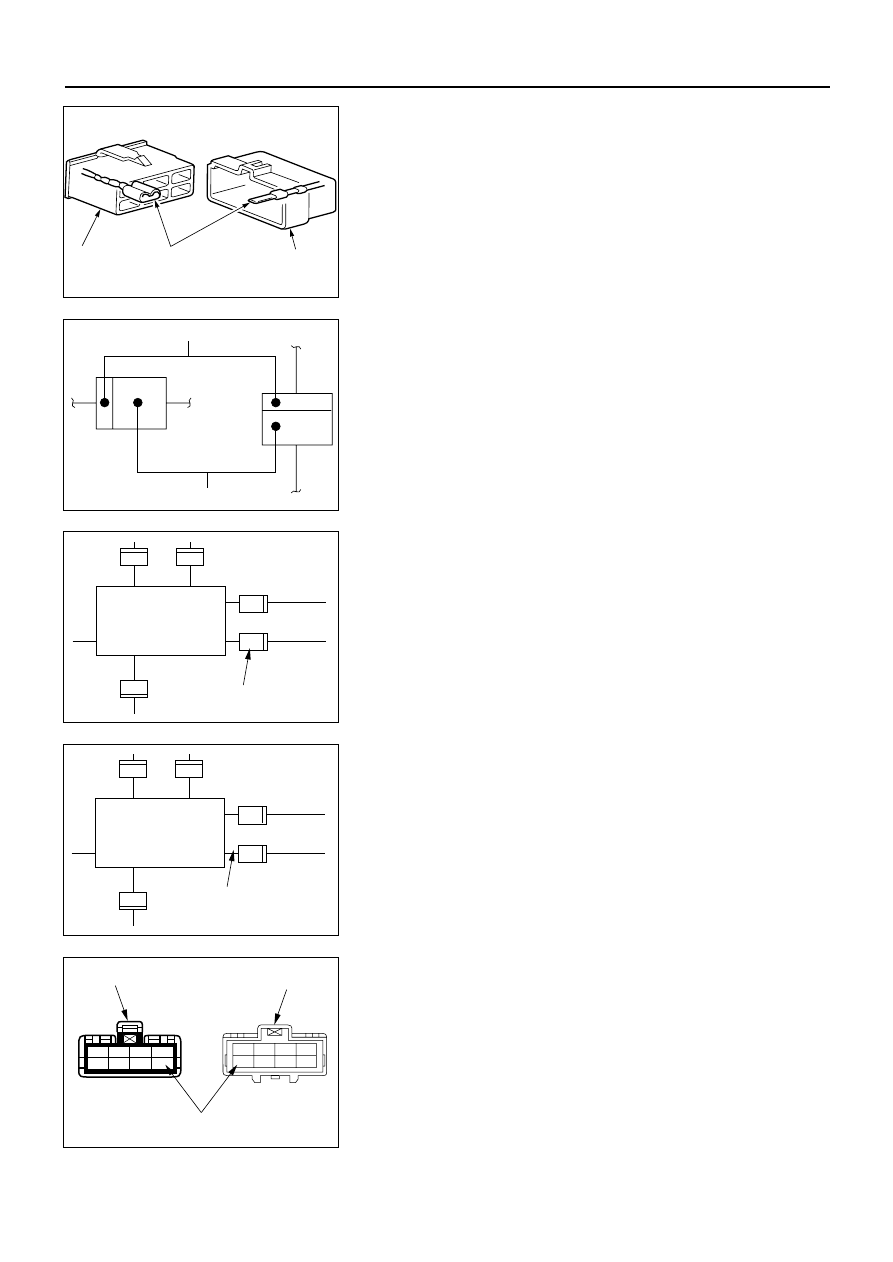
CONNECTOR
The connector pin shape determines whether the con-
nector is male or female.
The connector housing configuration does not determine
whether a connector is male or female.
Female
connector
Connector
pin shape
Male
connector
D08RV685
The symbol illustrated in the figure is used as connector
in the circuit of this section.
Female side connector
Male side connector
D08RV710
Connector is identified with a number.
W-38
5
W-38
7
W-38
1
W-38
6
4
W-38
SHIFT LOCK
Connector number
0.5R/L
0.85W/L
D08RV711
The applicable terminal number is shown for each
connector.
W-38
5
W-38
7
W-38
1
W-38
6
4
W-38
SHIFT LOCK
Terminal number
0.5R/L
0.85W/L
D08RV712
Connector terminal numbers are clearly shown.
Male side connector terminal numbers are in sequence
from upper right to lower left.
Female side connector terminal numbers are in sequence
from upper left to lower right.
NOTE:
For those connectors on which specific terminal numbers
on symbols are shown, the terminal numbers or symbols
are used in the circuit diagram, irrespective of the above
rule.
1
2
3
4
5
6
7
8
1
2
3
4
5
6
7
8
Male side connector
Female side connector
Terminal number
D08RV713
Нет комментариевНе стесняйтесь поделиться с нами вашим ценным мнением.
Текст