Isuzu D-Max / Isuzu Rodeo (TFR/TFS). Manual — part 1977
4C2-28 FRONT DRIVING AXLE
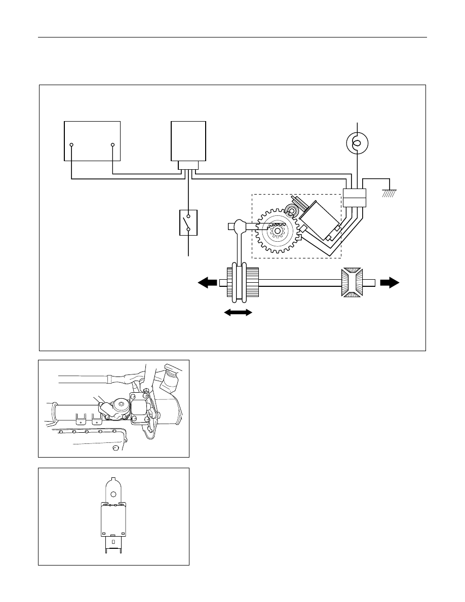
SHIFT ON THE FLY SYSTEM ELECTRIC EQUIPMENT
DIAGRAM
LH
RH
Battery
Axle Disconnect
Controller
4WD
Indicator
Axle Motor
Actuator
4x4
4WD
SW
4x2
ACTUATOR ASSEMBLY
Axle Disconnect Controller
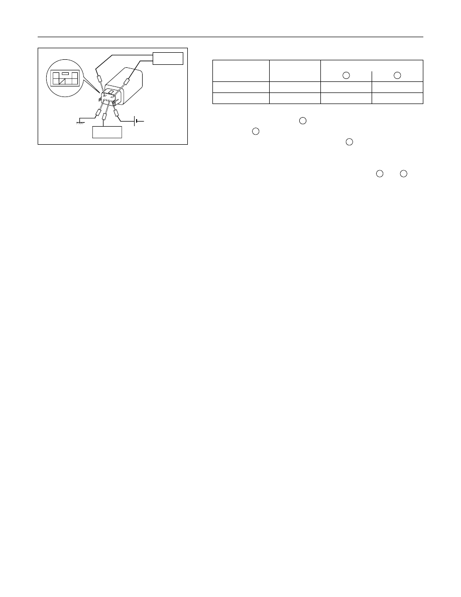
FRONT DRIVING AXLE 4C2-29
2
6 5
4 3
1
Terminal Arrangement
of Connector
Out signal
Input signal
GND
12V
Checking procedure for the controller’s trouble.
Input signal
1
2
2WD
→4WD
Hi
0V
12V
4WD
→2WD
Lo
12V
0V
Output signal
1. Connect the terminal
3
to the 12V pin, and connect the
terminal
6
to the ground (GND).
2. Apply the input signal to the terminal
4
.
2WD
→4WD
More than 9.0V
4WD
→2WD
Less than 1.5V
3. Make sure the output signal from the terminal
1
and
2
.
(The output signal is outputted for 2 seconds.)
TFSOF-WE-0091
You are requested to order this manual using the
manual number that is shown above.
This manual is applicable for vehicles in all countries
except the USA, and Canada.
All rights reserved. This manual may not be
reproduced in whole or in part, without the permission
in writing of ISUZU MOTORS LIMITED.
Issued by
ISUZU MOTORS LIMITED
INTERNATIONAL SERVICE DEPARTMENT
Shinagawa-ku, Tokyo 140-8722, Japan
Fax: +81-3-5471-1093
Tel: +81-3-5471-1315
First edition Aug., 1999
0911-01A-3
No. TFSOF-WE-0091
PRINTED IN JAPAN
Нет комментариевНе стесняйтесь поделиться с нами вашим ценным мнением.
Текст