Isuzu D-Max / Isuzu Rodeo (TFR/TFS). Manual — part 1349
8–316 ELECTRICAL-BODY AND CHASSIS
•
When there is no continuity at either one of the
circuit No. 5, 7, 8, or 10, the motor in the mirror of
the circuit or the circuit itself is defective.
Terminal
Wire
Connecting to
Check item
Connecting
Check condition
Standard
No.
color
terminal
1
B/W
LH mirror &
Continuity
1-Ground
—
No continuity
RH mirror
4
R/L
Fuse CB-19 (15A)
Voltage
4-Ground
Starter SW “ACC”
Approx.
position
12V
5
V
RH mirror-LH/RH
5 – 1
—
7
W/B
RH mirror-Up/Down
7 – 1
—
8
W/G
LH mirror-Up/Down
Continuity
8 – 1
—
Continuity
9
B
Ground
9-Ground
—
10
B/R
LH mirror-LH/RH
10 – 1
—
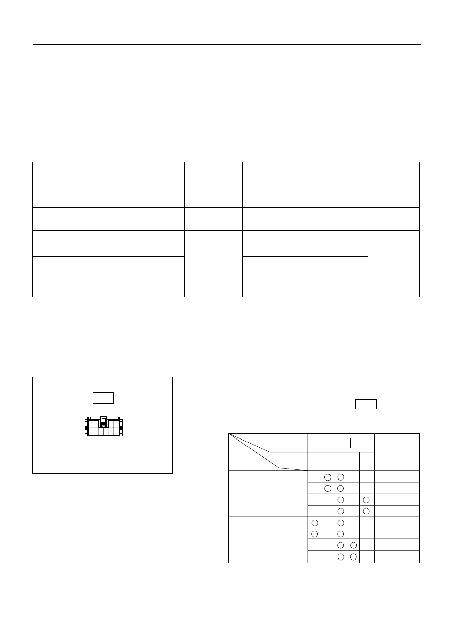
Door Mirror
1. Door Mirror Control Switch Connector Circuit
Disconnect the switch connector ( B-26 ), apply the
battery voltage to the harness side connector
terminals and check its function.
10
9
8
7
6
5
4
3
2
1
Harness side
B-26
Connector
No.
Operating
Terminal
10
5
1
8
7
direction
Mirror
No.
+
–
Left
Right
–
+
Right
–
+
Up
+
–
Down
+
–
Left
Left
–
+
Right
–
+
Up
+
–
Down
B-26
M
M
Down
RH
UP
3
1
2
LH
ELECTRICAL-BODY AND CHASSIS 8–317
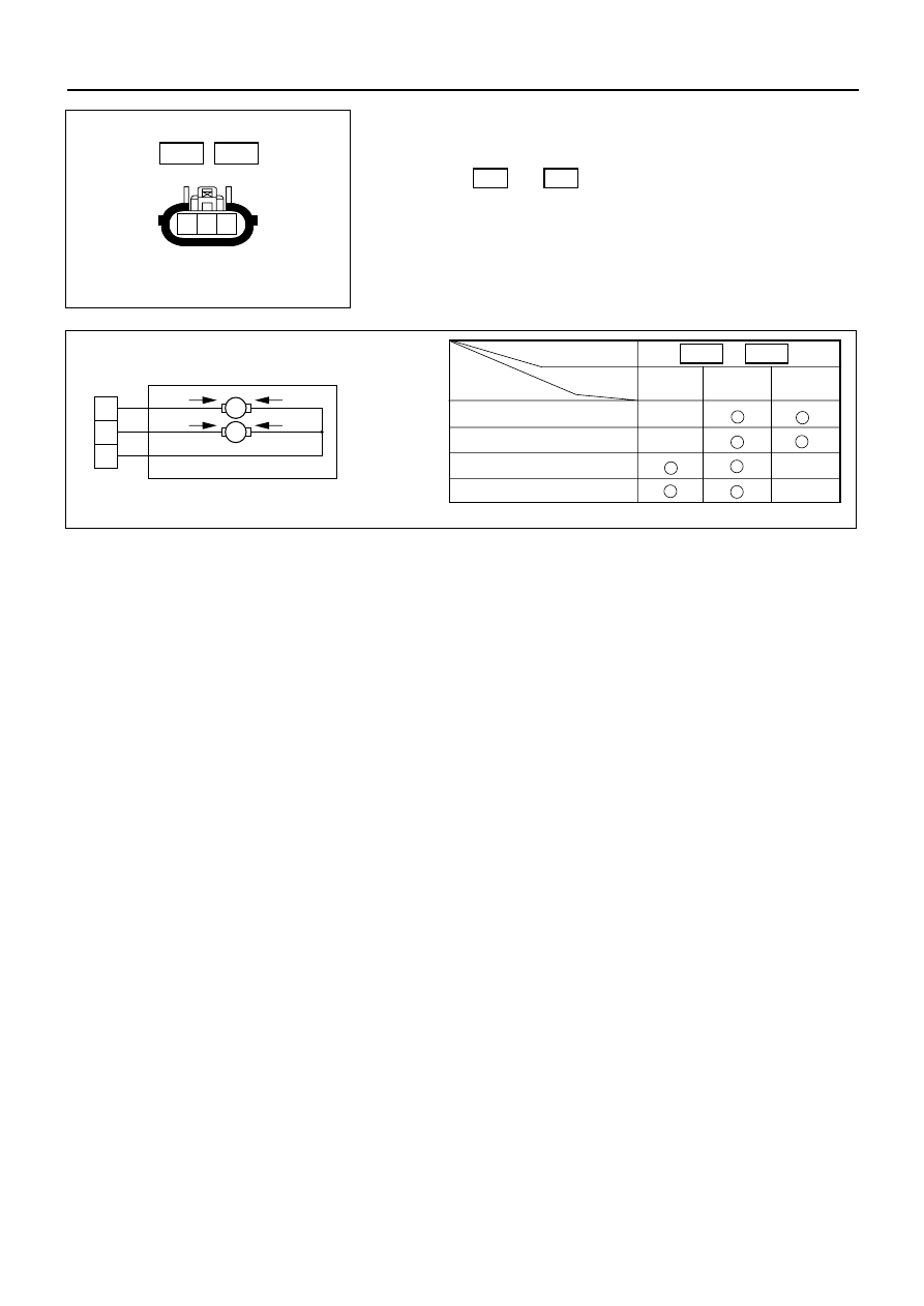
2. Door Mirror Connector Circuit
Disconnect the door mirror connector, apply the
battery voltage to the door mirror side connector
( D-2 and D-7 ) terminals and check its function.
1
2
3
825RV093
Door mirror side
D-2
D-7
Connector No.
Terminal
1
2
3
Operation
No.
Up
–
+
Down
+
–
Left
+
–
Right
–
+
D-2
D-7
8–318 ELECTRICAL-BODY AND CHASSIS
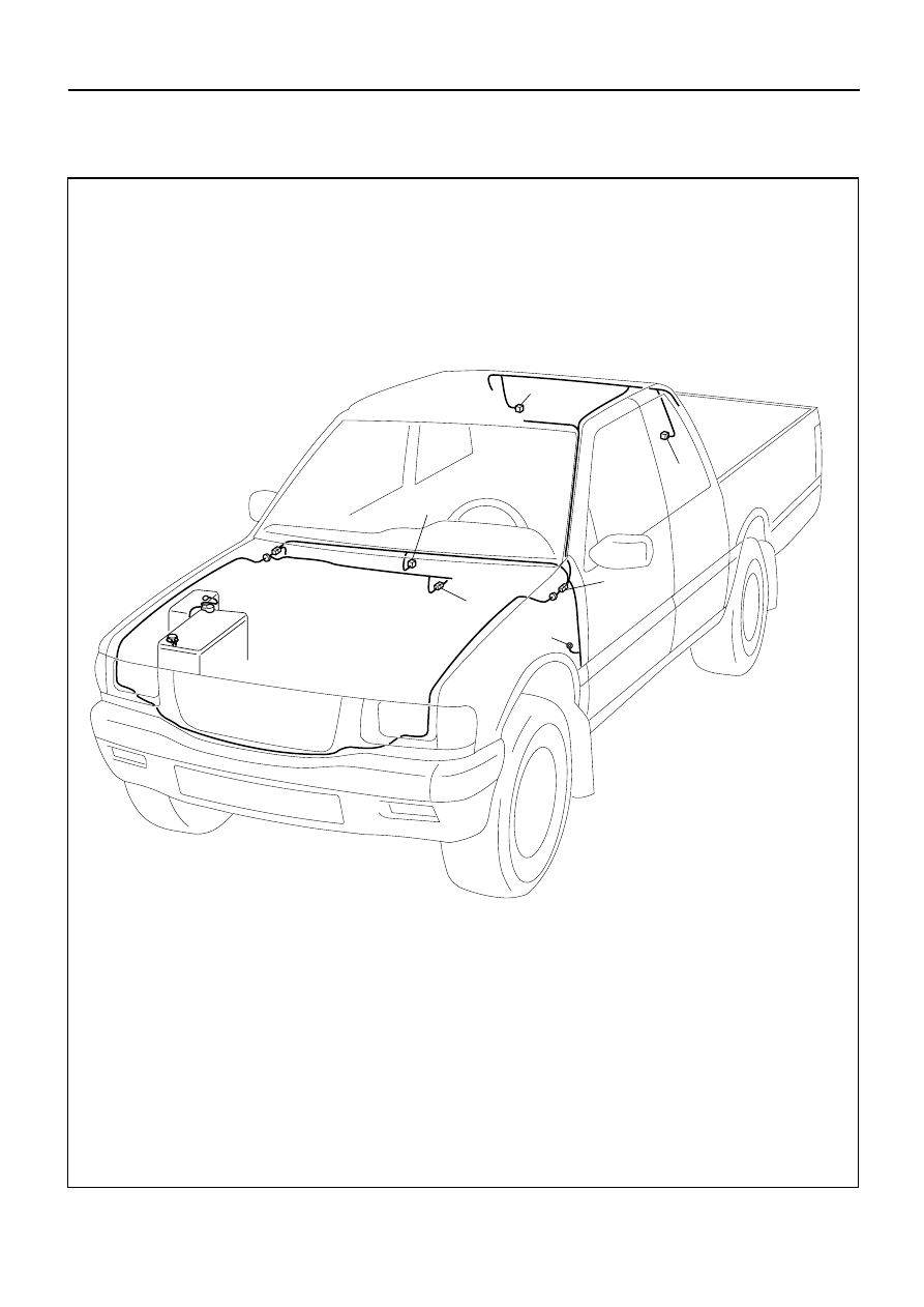
REAR DEFOGGER
PARTS LOCATION (LHD)
B-28
L-7
L-4
C-41
B-15
H-7
H-12
D08RVA46
ELECTRICAL-BODY AND CHASSIS 8–319
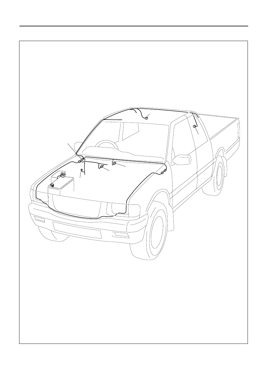
PARTS LOCATION (RHD)
L-4
L-7
C-41
B-15
B-28
H-7
H-12
D08RVA47
Нет комментариевНе стесняйтесь поделиться с нами вашим ценным мнением.
Текст