Isuzu D-Max / Isuzu Rodeo (TFR/TFS). Manual — part 1348
8–312 ELECTRICAL-BODY AND CHASSIS
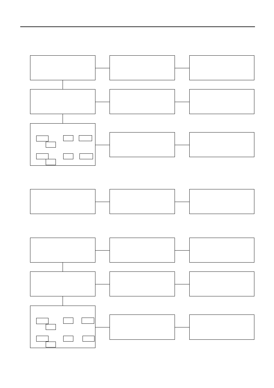
2.
Mirror on the left (or right) side does not operate
Checkpoint
Trouble Cause
Countermeasure
SW. malfunction
Replace the door mirror
control SW.
Door mirror control SW.
function
NG
OK
OK
Mirror malfunction on the
left (or right) side
Repair or replace the door
mirror
Mirror function on the left
(or right) side
NG
Open circuit or poor
connector contact
Repair open circuit or
connector contact
Continuity between
[LHD]
1 B-26 and 2 D-2 (1 B-26
and 2 D-7 )
[RHD]
1 B-26 and 2 D-7 (1 B-26
and 2 D-2 )
NG
3.
Mirrors on the both sides operate only in the vertical (or horizontal) direction
SW. malfunction
Replace the door mirror
control SW.
Door mirror control SW.
function
NG
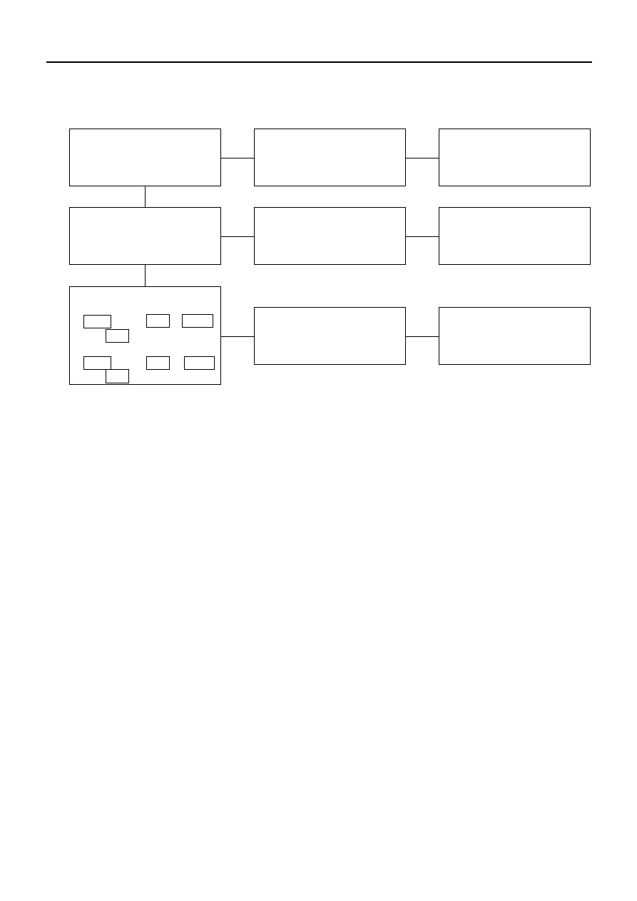
4.
Mirror on th left side operates only in the vertical (or horizontal) direction
SW. malfunction
Replace the door mirror
control SW.
Door mirror control SW.
function
NG
OK
OK
Door mirror malfunction
Repair or replace the door
mirror
Door mirror function
NG
Open circuit or poor
connector contact
Repair open circuit or
connector contact
Continuity between
[LHD]
8 B-26 and 3 D-2 (10 B-26
and 1 D-2 )
[RHD]
8 B-26 and 3 D-7 (10 B-26
and 1 D-7 )
NG
ELECTRICAL-BODY AND CHASSIS 8–313
5.
Mirror on the right side operates only in the vertical (or horizontal) direction
Checkpoint
Trouble Cause
Countermeasure
Door mirror control
malfunction
Replace the door mirror
control SW.
Door mirror control SW.
function
NG
OK
OK
Door mirror malfunction
Repair or replace the door
mirror
Door mirror function
NG
Open circuit or poor
connector contact
Repair open circuit or
connector contact
Continuity between
[LHD]
7 B-26 and 3 D-7 (5 B-26
and 1 D-7 )
[RHD]
7 B-26 and 3 D-2 (5 B-26
and 1 D-2 )
NG
8–314 ELECTRICAL-BODY AND CHASSIS
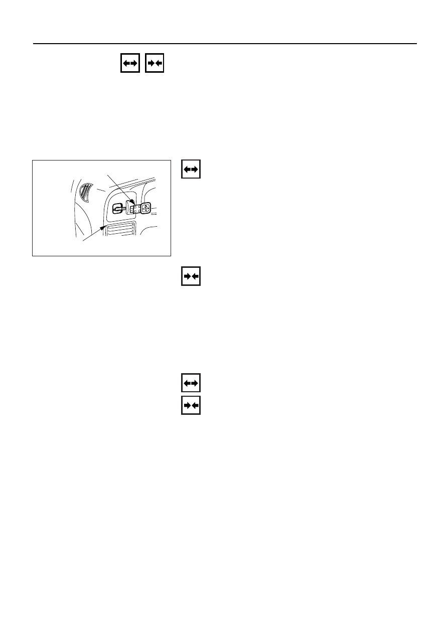
REMOVAL AND INSTALLATION
DOOR MIRROR CONTROL SWITCH
Removal
1. Instrument Panel Cluster Assembly
•
Refer to section 10 “BODY” for instrument panel
cluster assembly removal steps.
2. Door Mirror Control Switch
•
Disconnect the switch connector.
•
To remove the switch, push the lock from the back
side of the cluster assembly.
2. Door mirror control
switch
1. Instrument panel
cluster assembly
825RV094
Installation
To install, follow the removal steps in the reverse order.
DOOR MIRROR
Removal and Installation
Refer to the DOOR MIRROR in section 10 “BODY”.
ELECTRICAL-BODY AND CHASSIS 8–315
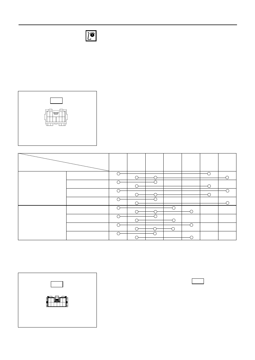
INSPECTION AND REPAIR
Door Mirror Control Switch
1. Switch Side Connector Circuit
Check continuity between the switch connector
terminals while operating the door mirror control
switch as shown in the following table.
1
2
5
6
7
8
9
10
3
4
Switch side
B-26
Connector No.
4
9
1
8
10
7
5
Switch position
(Up)
Door mirror (RH)
(Down)
(Left)
(Right)
(Up)
Door mirror (LH)
(Down)
(Left)
(Right)
2. Harness Side Connector Circuit
Remove the connector No. B-26 of the mirror
control switch and check voltage and continuity of
the harness side connector.
•
When there is no continuity at the terminal No. 5,
7, 8 and 10, it is considered that the circuit with
terminal No. 1 (B/W) is defective.
10
9
8
7
6
5
4
3
2
1
Harness side
B-26
▲
▲
▲ ▲
▲▲
▲▲
▲
▲
▲ ▲
▲▲
▲▲
Нет комментариевНе стесняйтесь поделиться с нами вашим ценным мнением.
Текст