Isuzu D-Max / Isuzu Rodeo (TFR/TFS). Manual — part 117

6E–72
4JH1 ENGINE DRIVEABILITY AND EMISSIONS
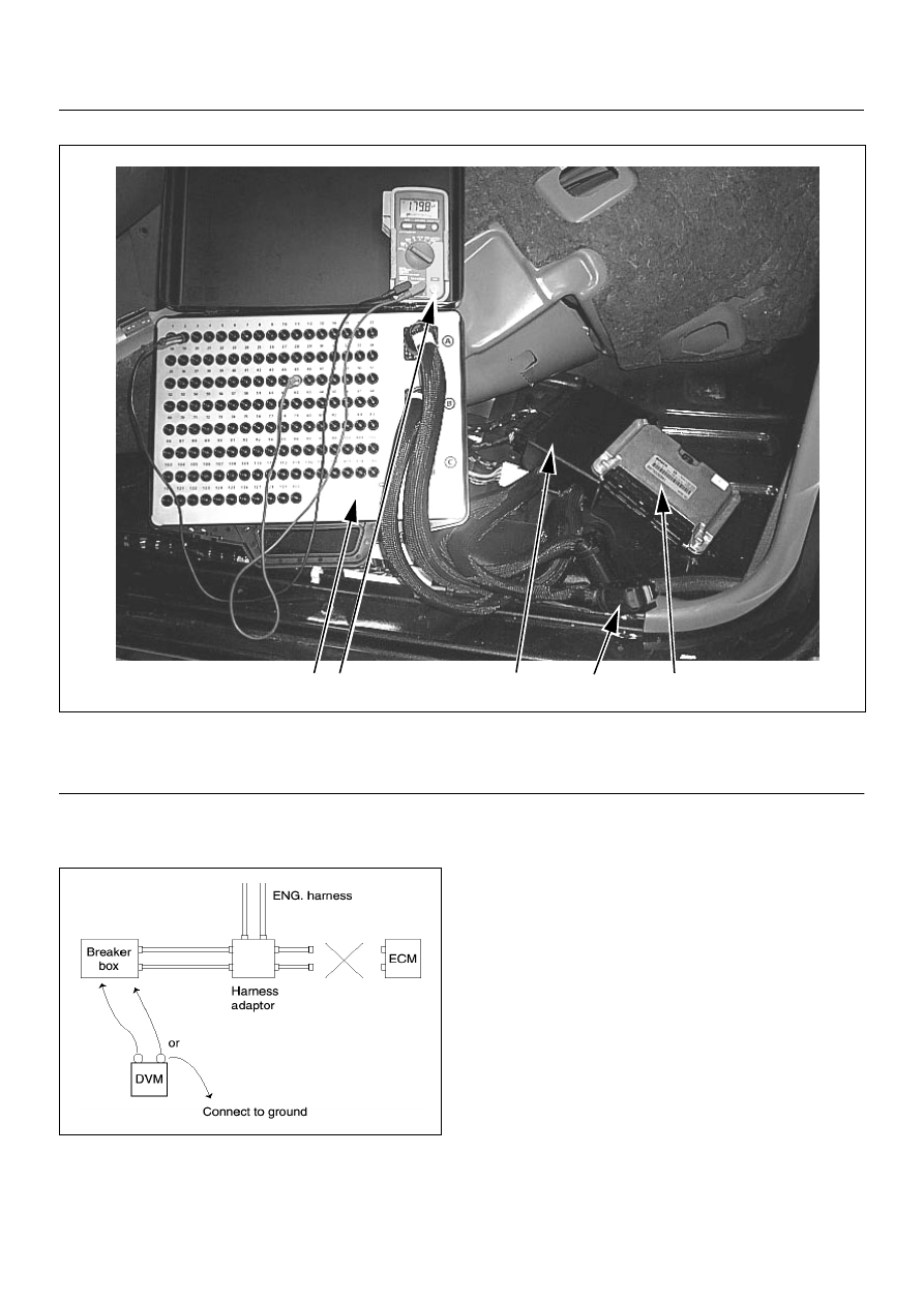
HOW TO USE BREAKER BOX
The engine control module (ECM) and other connectors
have water proof connector and special terminal. Water
proof terminal does not allow to use back prove. In
addition, the engine control module (ECM) special
terminal can not let regular digital voltage meter prove to
access, because terminal shape is very fin pin type.
In order to prevent damage of female terminal and
connector itself, the breaker box and adapter is the most
suitable special tool.
3
1
2
(1) Engine Control Module (ECM)
(2) Harness Adapter
(3) Breaker Box
4JH1 ENGINE DRIVEABILITY AND EMISSIONS
6E–73
Breaker Box Connection Type A
Breaker box connection type A, check for “open circuit”
and “short to ground circuit”.
4
3
5
1
2
(1) Engine Control Module (ECM)
(2) Harness Adapter
(3) Breaker Box
(4) Digital Voltage Meter
(5) ECM - Harness Adapter Disconnection

6E–74
4JH1 ENGINE DRIVEABILITY AND EMISSIONS
Breaker Box Connection Type B
Breaker box connection type B, check for “short to
power supply circuit” and “power, signal voltage check”
between the engine control module (ECM) and
electrical components.
4
3
2
5
1
(1) Engine Control Module (ECM)
(2) Harness Adapter
(3) Breaker Box
(4) Digital Voltage Meter
(5) ECM - Harness Adapter Connection
4JH1 ENGINE DRIVEABILITY AND EMISSIONS
6E–75
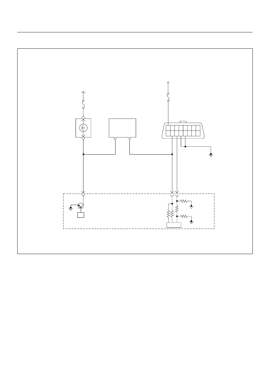
ON-BOARD DIAGNOSTIC (OBD) SYSTEM CHECK
Circuit Description
The on-board diagnostic system check is the starting
point for any driveability complaint diagnosis. Before
using this procedure, perform a careful visual/physical
check of the ECM and engine grounds for cleanliness
and tightness.
The on-board diagnostic system check is an organized
approach to identifying a problem created by an
electronic engine control system malfunction.
Diagnostic Aids
An intermittent may be caused by a poor connection,
rubbed-through wire insulation or a wire broken inside
the insulation. Check for poor connections or a
damaged harness. Inspect the ECM harness and
connector for improper mating, broken locks, improperly
formed or damaged terminals, poor terminal-to-wire
connection, and damaged harness.
Test Description
Number(s) below refer the step number(s) on the
Diagnostic Chart:
1. The Check Engine Lamp (MIL) should be ON steady
with the ignition “On”, engine “Off”. If not, “No Check
Engine Lamp (MIL)” chart should be used to isolate the
malfunction.
2. Checks the Class 2 data circuit and ensures that the
ECM is able to transmit serial data.
3. This test ensures that the ECM is capable of
controlling the Check Engine Lamp (MIL) and the Check
Engine Lamp (MIL) driver circuit is not shorted to
ground circuit.
4. If the engine will not start, “Engine Cranks But Will
Not Run” chart should be used to diagnose the fault.
µP
1.25
BLK
16 15 14 13 12 11 10 9
8 7 6 5 4 3 2 1
0.5
RED/
YEL
0.5
WHT
0.5
BLU
35
45
0.5
BRN/
YEL
42
IC
Meter
10A
Meter
15A
Ignition
SW
Check
Engine
Lamp
Imnobiliser
Control Unit
Butery
Voltage
7
8
Engine
Control
Module
(ECM)
Нет комментариевНе стесняйтесь поделиться с нами вашим ценным мнением.
Текст