Isuzu D-Max / Isuzu Rodeo (TFR/TFS). Manual — part 118

6E–76
4JH1 ENGINE DRIVEABILITY AND EMISSIONS
6. The Tech2 parameters which is not within the typical
range may help to isolate the area which is causing the
problem.
12. This vehicle is equipped with ECM which utilizes an
electrically erasable programmable read only memory
(EEPROM).
On-Board Diagnostic (OBD) System Check
Step
Action
Value(s)
Yes
No
1
1. Ignition “On”, engine “Off”.
2. Check the “CHECK ENGINE” lamp (MIL).
Does the “CHECK ENGINE” lamp turn “On”?
—
Go to Step 2
Go to No
CHECK
ENGINE Lamp
2
1. Using the Tech 2, ignition “On” and engine “Off”.
2. Attempt to display “Data Display” with the Tech 2.
Does the Tech 2 display engine data?
—
Go to Step 3
Go to Step 7
3
1. Using the Tech 2, ignition “On” and engine “Off”.
2. Select the “Miscellaneous Test” and perform the
“Check Light” in “Lamps”.
3. Operate the Tech 2 in accordance with the Tech 2
instructions.
Does the “CHECK ENGINE” lamp turn “Off”?
—
Go to Step 4
Go to CHECK
ENGINE LAMP
On Steady
4
Attempt to start the engine.
Does the engine start and continue to “Run”?
—
Go to Step 5
Go to Engine
Cranks But Will
Not Run
5
1. Using the Tech 2, ignition “On” and engine “Off”.
2. Select the “Read DTC Infor As Stored By ECU” in
“Diagnostic Trouble Code”.
3. Are any DTCs stored?
—
Go to DTC
Chart
Go to Step 6
6
Compare typical scan data values displayed on the
Tech 2 “Data Display”.
Are the displayed values within the range?
—
Refer to
SYMPTOM
DIAGNOSIS
Refer to
TYPICAL
SCAN DATA
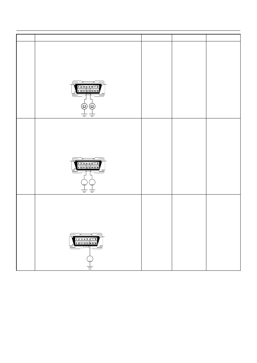
7
Using the DVM and check the data link connector
power supply circuit.
1. Ignition “Off”, engine “Off”.
2. Check the circuit for open circuit.
Was the problem found?
—
Repair faulty
harness and
verify repair
Go to Step 8
V
16
B-58
4JH1 ENGINE DRIVEABILITY AND EMISSIONS
6E–77
8
Using the DVM and check the data link connector
ground circuit.
1. Ignition “Off”, engine “Off”.
2. Check the circuit for open circuit.
Was the problem found?
—
Repair faulty
harness and
verify repair
Go to Step 9
9
Using the DVM and check the data link connector
ground circuit.
1. Ignition “On”, engine “Off”.
2. Check the circuit for short to power supply circuit.
Was the DVM indicated specified value?
Less than 1V
Go to Step 10
Repair faulty
harness and
verify repair
10
Using the DVM and check the data link connector
communication circuit.
1. Ignition “On”, engine “Off”.
2. Check the circuit for short to power supply circuit.
Was the DVM indicated battery voltage?
—
Repair faulty
harness and
verify repair
Go to Step 11
Step
Action
Value(s)
Yes
No
5
4
B-58
V
V
5
4
B-58
V
6
B-58

6E–78
4JH1 ENGINE DRIVEABILITY AND EMISSIONS
11
Using the DVM and check the data link connector
communication circuit.
1. Ignition “Off”, engine “Off”.
2. Disconnect the ECM connector.
3. Check the circuit for open or short to ground
circuit.
Was the problem found?
—
Repair faulty
harness and
verify repair
Go to Step 12
12
Is the ECM programmed with the latest software
release?
If not, download the latest software to the ECM using
the “SPS (Service Programming System)”.
Was the problem solved?
—
Verify repair
Go to Step 13
13
Replace the ECM.
Is the action complete?
IMPORTANT: The replacement ECM must be
programmed. Refer to section of the Service
Programming System (SPS) in this manual.
Following ECM programming, the immobiliser system
(if equipped) must be linked to the ECM. Refer to
section 11 “Immobiliser System-ECM replacement” for
the ECM/Immobiliser linking procedure.
—
Verify repair
—
Step
Action
Value(s)
Yes
No
6
45
B-58
C-56
4JH1 ENGINE DRIVEABILITY AND EMISSIONS
6E–79
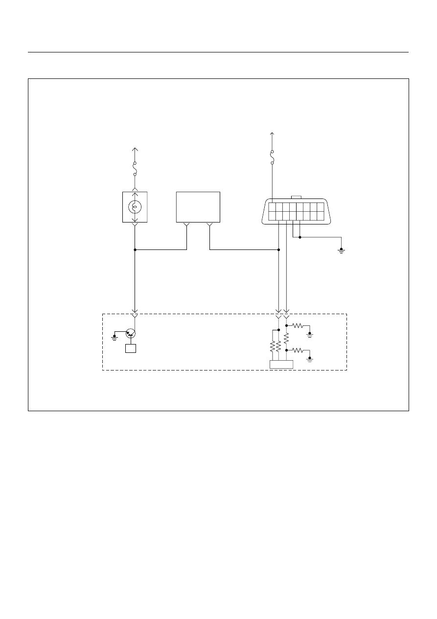
NO CHECK ENGINE LAMP (MIL)
Circuit Description
The check engine lamp should be illuminated and
steady for about five seconds with the ignition “ON” and
the engine stopped. Ignition feed voltage is supplied to
the check engine lamp bulb through the meter fuse.
The Engine Control Module (ECM) turns the check
engine lamp “ON” by grounding the check engine lamp
driver circuit.
Diagnostic Aids
An intermittent check engine lamp may be cased by a
poor connection, rubbed-through wire insulation, or a
wire broken inside the insulation. Check for the
following items:
• Inspect the ECM harness and connections for
improper mating, broken locks, improperly formed or
damaged terminals, poor terminal-to-wire
connection, and damaged harness.
• If the engine runs OK, check for a faulty light bulb, an
open in the check engine lamp driver circuit, or an
open in the instrument cluster ignition feed.
• If the engine cranks but will not run, check for an
open ECM ignition or battery feed, or a poor ECM to
engine ground.
µP
1.25
BLK
16 15 14 13 12 11 10 9
8 7 6 5 4 3 2 1
0.5
RED/
YEL
0.5
WHT
0.5
BLU
35
45
0.5
BRN/
YEL
42
IC
Meter
10A
Meter
15A
Ignition
SW
Check
Engine
Lamp
Imnobiliser
Control Unit
Butery
Voltage
7
8
Engine
Control
Module
(ECM)
Нет комментариевНе стесняйтесь поделиться с нами вашим ценным мнением.
Текст