Isuzu D-Max / Isuzu Rodeo (TFR/TFS). Manual — part 947
REAR AXLE 4B-25
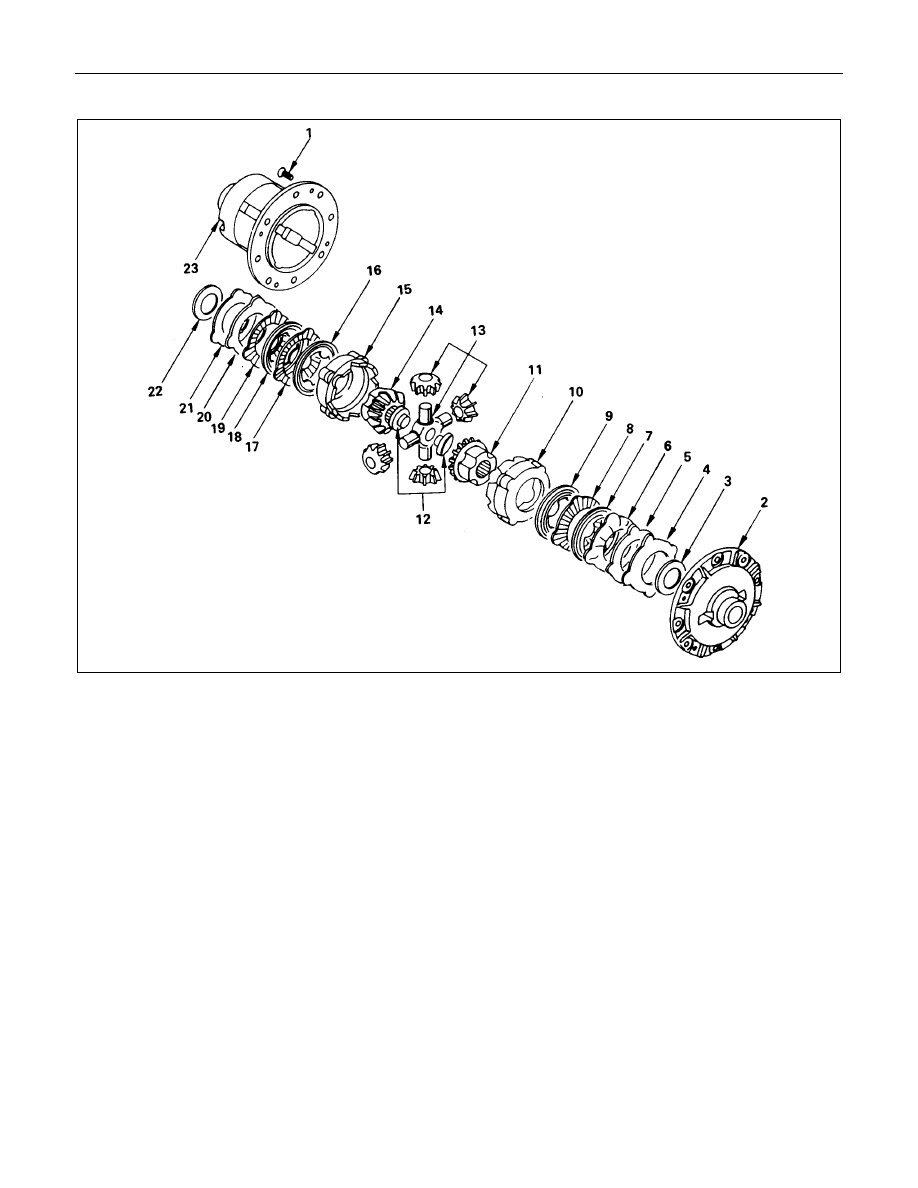
(FOR RING SIZE 220 mm)
Disassembly Steps
▲
1. Bolt
2. Differential cage cover
3. Thrust washer
4. Bellve disc
5. Bellve disc
6. Friction plate
7. Friction disc
8. Friction plate
9. Friction disc
10. Pressure ring
11. Side gear
12. Thrust block
13. Pinion gear and pinion spider
14. Side gear
15. Pressure ring
16. Friction disc
17. Friction plate
18. Friction disc
19. Friction plate
20. Bellve disc
21. Bellve disc
22. Thrust washer
23. Thrust washer
4B-26 REAR AXLE
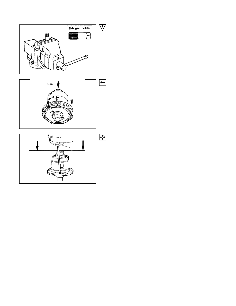
Important Operations
•
Prepare a side gear holder (An axle shaft must be used) as
shown in the left figure, clamp it with a stock vice, and set a
differential.
1. Bolt
Apply a setting mark to the differential cage cover and
differential cage a remove the bolt using the press.
•
When the differential cage is pressed down with the press,
loosen the four bolts fixing the differential cage evenly and
remove them, and then disconnect the differential cage.
REAR AXLE 4B-27
INSPECTION AND REPAIR
Make all necessary adjustments, repairs, and part replacements if wear, damage, or other problems are discovered
during inspection.
•
Gear
•
Bearing
•
Differential box
•
Drive pinion
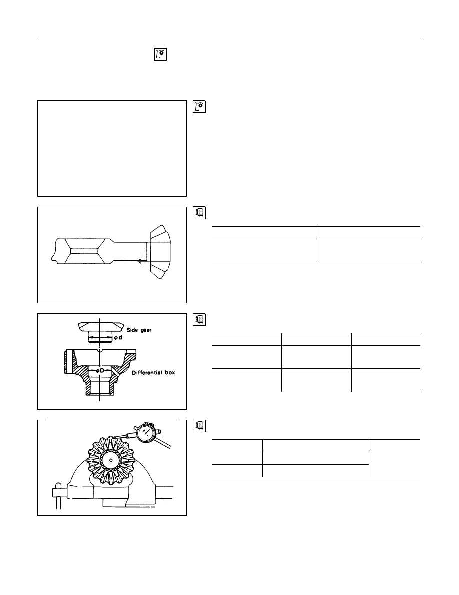
Visual Check
Inspect the following parts for wear, damage or other abnormal
conditions.
Clearance between pinion gear and cross pin:
194 mm and 220 mm
mm(in)
Standard
Limit
0.06 - 0.12
(0.002 - 0.005)
0.2 (0.008)
Clearance between side gear and differential cage.
mm(in)
Standard
Limit
194 mm
0.03 - 0.10
(0.001 - 0.004)
0.15 (0.006)
220 mm
0.05 - 0.11
(0.002 - 0.004)
0.15 (0.006)
Play in splines between the side gear and axle shafts.
mm(in)
Standard
Limit
194 mm
0.08 - 0.36 (0.003 - 0.014)
220 mm
0.08 - 0.38 (0.003 - 0.015)
0.5 (0.02)
4B-28 REAR AXLE
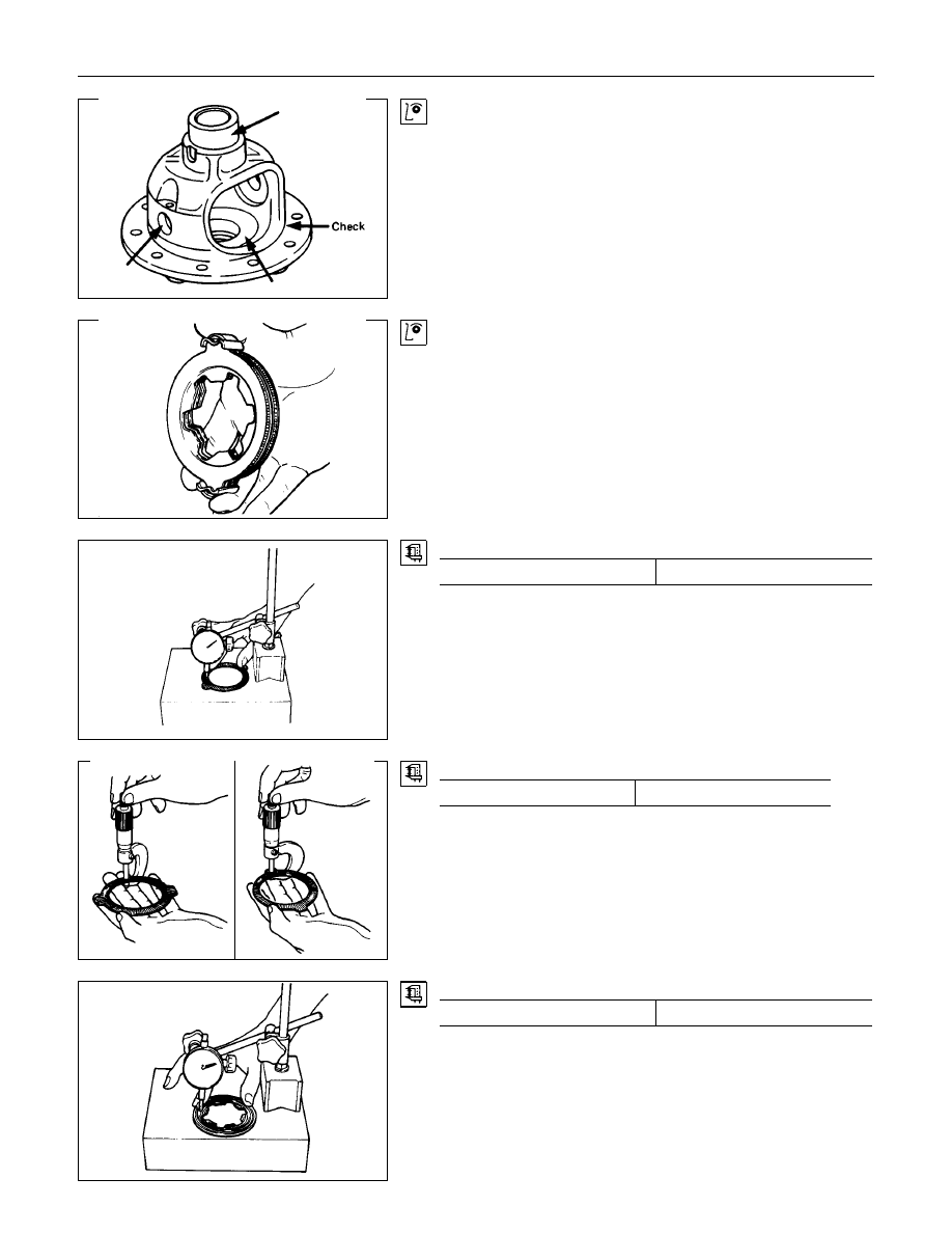
Differential cage
Check the ring gear the side gear fitting faces and the cross pin
hole for scores or roughness. Correct as necessary. Slight
scores or roughness may be corrected with an oil stone or fine
sand paper.
<LSD FOR 194 mm>
Friction disc and plate assembly.
Check the parts for damage or other abnormal conditions.
Check the friction plate for distortion.
Limit
mm(in)
0.07 (0.0027)
Check the friction plate for wear.
Limit (A - B)
mm(in)
0.1 (0.0039)
Note : A = Non-sliding face thickness
B = Sliding face thickness
Check the friction disc for distortion.
Limit
mm(in)
0.07 (0.0027)
Нет комментариевНе стесняйтесь поделиться с нами вашим ценным мнением.
Текст